Other Parts Discussed in Thread: TAS6422-Q1
Hi, Support Team
our software team have a question:
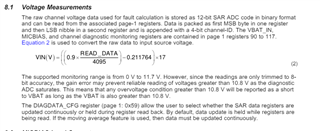
if ADC(PCM6020-Q1) can read voltage vaule.
how to mapping digital signal related voltage value?
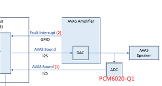
function block:
if any suggestion, Please advise me.
Thanks,
Best regards,
Lawrence

 \
\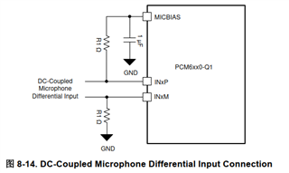
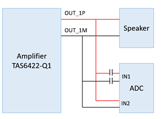
 Image Source: