A related question is a question created from another question. When the related question is created, it will be automatically linked to the original question.
If you have a related question, please click the "Ask a related question" button in the top right corner. The newly created question will be automatically linked to this question.
If you are recording DC offset then there is likely a high pass filter missing in the chain or there is error in the biasing point of the ADC versus where the signal is biased to. If it is an issue you will need to share more details about the circuit set up and how you are recording the data.
Hi Jeff, Thank you for your reply. Here are more details:
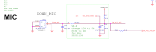
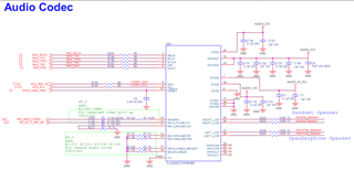
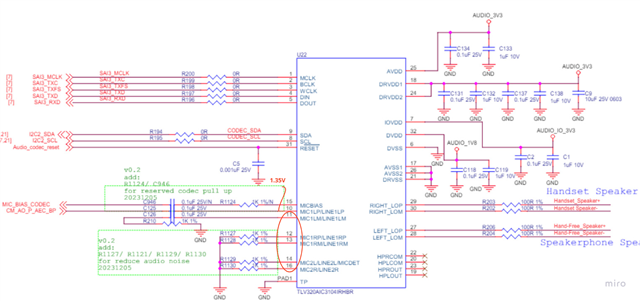
1. For the circuit set, our MIC bias is powered by an external LDO at 3.3V, and it's also connected to the codec AVDD power supply.
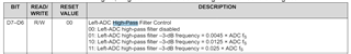
2. The AC-coupling capacitor uses 0.1uF, and the input level control is set at 0dB. This results in a high-pass filter pole of 80 Hz. I've tried using a 0.2uF AC-coupling capacitor, which lowered the high-pass filter pole to almost 40Hz, but it also introduced a DC offset.
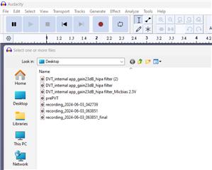
3.We use a recording app developed for the Android system. This app allows us to convert a . PCM file to a . WAV file directly. Then, we use the Audacity app to analyze it.
if need more information about it please just let me know so I can ask to our software
Thanks, Jeff. I've successfully configured it. However, I'm curious about what caused the DC offset. Is this normal or is there anything I should be aware of circuit?
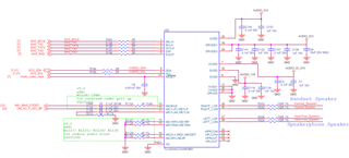
Your DC offset looked small which is quite normal. In the real world, unmatched coupling caps, non linearities, and other non-ideal situations can cause DC offset in the recording. That's why the high pass filter is there, to help remove those things. I don't see anything wrong in the schematic.
Hi Jeff, Understood. So, if I've turned on the high-pass filter and there's a slight DC offset, does this mean I need to try a different cut-off frequency?
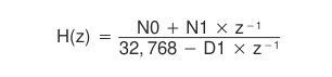
Thank you for your advice. I've tried the other options for the high pass filter as you suggested. I enabled the high filter by writing to page 0, register 12, then selected the programmed coefficients by writing to page 0, register 107, and used the default values.
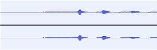
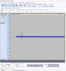
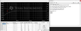
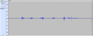
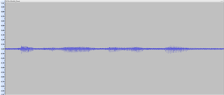
To review the results, I utilized Audacity as a tool to open the .wav file I recorded from our device.
Did using the other options help the DC offset? If you're using default coefficients, there's no need to select "programmed coefficients" in register 107. The preprogrammed options in register 12 should be enough. If the issue persists, how is the .wav file being recorded?
Another check you can do is measure the analog signal input for any DC offset. If it is not present in the analog input, it is incredibly unlikely it is being generated from the device. It is more likely to be a recording issue in that case.
Hi Jeff, 1. I've measured pin 10, which we've set as signal end input, and it's at 1.35V. Is this normal? Also, based on your suggestion, I understand that I can check other inputs like pin11, pin12, pin13, pin14, and pin16 for any DC offset, correct?
2. We use a recording app developed for the Android system. This app lets us directly convert a . PCM file to a . WAV file. have any information I need to provide like convert format?
The 1.35V offset is normal. Have you ruled out that the .PCM to .WAV file conversion is not introducing an offset?
If you give me your I2C configuration script (not a register map, a sequence of I2C writes) I can try it on my EVM and see if I measure any offset. I can measure the PCM data directly.
Apologies for the late reply due to busy work schedules. We've finally resolved the issues by enabling the high-pass filter through the software driver, not the command line.