This thread has been locked.

If you have a related question, please click the "Ask a related question" button in the top right corner. The newly created question will be automatically linked to this question.

TLV320AIC3104: Setting PGA gain without clock. Recording doesn't work

Part Number: TLV320AIC3104

Tool/software:

Dear forum users,

I would like to use TLV320AIC3104 IC for music playing and voice recording.
I connect a Feasycom bluetooth module to the codec via I2S. The clock source for the codec is the BCLK from the bluetooth module. I use Internal PLL to get the correct clock for ADC and DAC.
Audio data is configured for 48khz, 32 bit, stereo.

Playing seems to be working fine, playing a sine wave works.

I connected sine wave (line level output of celllphone) to the MIC2L/LINE2L input.

Issue1: Bluetooth module only generates clock if there is a recording or playing. It seems that configuring PGA requires clock. I can configure DAC, output drivers, I2S parameters without clock, but PGAs gain doesn't change if there is no clock. I would like to make configuration after booting my device, before any bluetooth connection. Am I doing something wrong, or this is normal behaviour? I can't find this information in the datasheet.(I checked PGA operation with routing PGA output to lineout)
Issue2: while recording, I hear creaking and chunky sound instead of clear sine wave. I configure registers during active Bluetooth connection to make sure that TLV320 has clock. I tried to route same signal to left and right ADC too, but did not helped.


Here is my configuration for checking PGA:
0: 0
2: 0
3: 0b10000001
4: 32 << 2
7: 0b00001010
9: 0b00110000
10: 1
11: 1
86: 0b00001001
93: 0b10011001
101: 0
102: 0b10100010
81: 0b10000000
17: 0b00001111
15: 0b01000001


Here is my configuration for checking recording:
0: 0
2: 0
3: 0b10000001
4: 32 << 2
7: 0b00001010
9: 0b00110000
10: 1
11: 1
101: 0
102: 0b10100010
17: 0b00001111
19: 0b11111111
15: 0b01000001


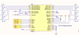
Sine wave is connected to "MIC" label now for testing.

  • Hi Balint,

    First, do you have PGA soft stepping enabled? It is enabled by default. This feature locks gain changes to ADC/DAC output samples, meaning that clocks are required for the gain change to take effect:

    "The PGA gain changes are implemented with an internal soft-stepping algorithm that only changes the actual volume level by one 0.5-dB step every one or two ADC output samples, depending on the register programming (see page 0, registers 19 and 22). This soft-stepping ensures that volume control changes occur smoothly with no audible artifacts."

    For the creaking issue, I would not use your phone as a generator during testing. I would use a function generator that you might find in a lab to ensure that the signal source is very clean. How are you listening to the sound?

    Best regards,
    Jeff McPherson

  • Hello,

    Thanks for reply.

    I tried to disable left and right soft stepping with writing R19-D1D0 and R22-D1D0 to 11, but it did not help.

    Issue2 is solved: value of Audio Serial Data Word Offset Control was incorrect.

  • Hi Balint,

    Can you clarify which clocks are being provided by the bluetooth module?

    Thanks,
    Jeff McPherson

  • Bluetooth module provides BCLK.
    MCLK input of the codec is not connected.

  • Hi Balint,

    I tried this out on an EVM and am seeing the PGA change gain, even with all I2S Clocks removed (including BCLK).

    Could you share with me your full device configuration steps so I can try to recreate the issue?

    Thanks,
    Jeff McPherson

  • Hi Jeff,

    Please, check this link: https://e2e.ti.com/support/audio-group/audio/f/audio-forum/185817/tlv320aic3104---adc-pga-gain-in-analog-bypass-mode

    The user could not set the PGA gain is there was no MCLK.

    Here is my device configuration:

    #define PAGE_SELECT 0
    #define SOFTWARE_RESET 1
    #define CODEC_SAMPLE_RATE_SELECT 2
    #define PLL_PROGRAMMING_A 3
    #define PLL_PROGRAMMING_B 4
    #define CODEC_DATA_PATH_SETUP 7
    #define AUDIO_SERIAL_DATA_INTERFACE_CONTROL_B 9
    #define AUDIO_SERIAL_DATA_INTERFACE_CONTROL_C 10
    #define AUDIO_CODEC_OVERFLOW_FLAG 11
    #define LEFT_ADC_PGA_GAIN_CONTROL 15
    #define RIGHT_ADC_PGA_GAIN_CONTROL 16
    #define MIC2LR_TO_LEFT_ADC_CONTROL 17
    #define MIC2LINE2_TO_RIGHT_ADC_CONTROL 18
    #define MIC1LPLINE1LP_TO_LEFT_ADC_CONTROL 19
    #define MIC1RPLINE1RP_TO_RIGHT_ADC_CONTROL 22
    #define MICBIAS_CONTROL 25
    #define LEFT_AGC_CONTROL_A 26
    #define LEFT_AGC_CONTROL_B 27
    #define LEFT_AGC_CONTROL_C 28
    #define RIGHT_AGC_CONTROL_A 29
    #define RIGHT_AGC_CONTROL_B 30
    #define RIGHT_AGC_CONTROL_C 31
    #define LEFT_AGC_NOISE_GATE_DEBOUNCE 34
    #define RIGHT_AGC_NOISE_GATE_DEBOUNCE 35
    #define DAC_POWER_AND_OUTPUT_DRIVER_CONTROL 37
    #define DAC_OUTPUT_SWITCHING_CONTROL 41
    #define OUTPUT_DRIVER_POP_REDUCTION 42
    #define LEFT_DAC_DIGITAL_VOLUME_CONTROL 43
    #define RIGHT_DAC_DIGITAL_VOLUME_CONTROL 44
    #define DAC1_L1_TO_LEFT_LOPM_VOLUME_CONTROL 82
    #define LEFT_LOPM_OUTPUT_LEVEL_CONTROL 86
    #define DAC_R1_TO_RIGHT_LOPM_VOLUME_CONTROL 92
    #define RIGHT_LOPM_OUTPUT_LEVEL_CONTROL 93
    #define CLOCK 101
    #define CLOCK_GENERATION_CONTROL 102
    #define PASSIVE_ANALOG_SIGNAL_BYPASS 108


    writeByteCodec(PAGE_SELECT,0);
    writeByteCodec(CODEC_SAMPLE_RATE_SELECT,0);//sample rate 48kHz for ADC and DAC
    writeByteCodec(PLL_PROGRAMMING_A, 0b10000001);//PLLEN=1|PLLQ=0000|PLLP=001
    writeByteCodec(PLL_PROGRAMMING_B,32<<2);//PLLJ=32
    writeByteCodec(CODEC_DATA_PATH_SETUP,0b00001010);
    writeByteCodec(AUDIO_SERIAL_DATA_INTERFACE_CONTROL_B,0b00110000);//mode=I2S|word lenght=32bit
    writeByteCodec(AUDIO_SERIAL_DATA_INTERFACE_CONTROL_C,0);//data offset=0 clock
    writeByteCodec(AUDIO_CODEC_OVERFLOW_FLAG,1);//PLL R = 1
    writeByteCodec(LEFT_LOPM_OUTPUT_LEVEL_CONTROL,0b00001001);//LEFT LOP gain 0dB|unmuted|fully powered
    writeByteCodec(CLOCK,0);//CODEC_CLKIN uses PLLDIV_OUT
    writeByteCodec(CLOCK_GENERATION_CONTROL,0b10100010);//CLKDIV_IN uses MCLK|PLLCLK_IN uses BCLK|reserved
    writeByteCodec(81,0b10000000);//PGA_L is routed to LEFT_LOP/M
    writeByteCodec(MIC2LR_TO_LEFT_ADC_CONTROL,0b00001111);//MIC2L is connected to PGA
    writeByteCodec(MIC1LPLINE1LP_TO_LEFT_ADC_CONTROL,0b11111111);//Left PGA soft stepping disabled
    writeByteCodec(LEFT_ADC_PGA_GAIN_CONTROL,0b00110001);left PGA enabled, and gain set

  • Hi Balint,

    I set up your code on an EVM and recreated the issue. I found that if clocks were not applied at start up, the gain would be stuck at 0dB like you described. As soon as clocks were applied the gain updated to the correct value. Furthermore, once clocks were taken away, the PGA would continue to update.

    So there is a limitation in the device that the PGA gain will be locked until clocks are applied, probably due to the fact that soft stepping is enabled by default as soon as the device is turned on. Without the clocks at startup, the soft stepping logic might be getting locked until clocks are applied, stopping the gain from changing. Normally this is not an issue because the ADC will not work, but in the case of the bypass path it becomes a limitation. However as soon as the I2S clocks are given, the gain will update, and continue to update correctly even once clocks are removed again (soft stepping disabled).

    Best regards,
    Jeff McPherson