PCM1821: audio input level check & confirm

Part Number: PCM1821
Other Parts Discussed in Thread: PCM1822

Tool/software:

Hi Sir,

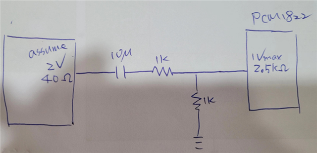
  We have a new opportunity to develop headphones for airline use, which will include an ADC chipset for audio analog input. However, I am unsure about the input voltage and how to select it for production.

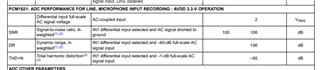
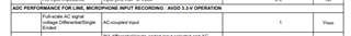
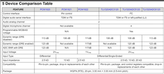
It looks like there are 2Vrms and 1Vrms input voltage ranges available. Which one would be better for ARINC C2 input? Could you provide some suggestions for this? a few conditions constrain as below:

1: Single-end (ARINC C2) audio input

2: I2S out

3: Pin control only

Thanks,

Danny

  • Hi Danny,

    The PCM1821 supports a differential voltage swing of 2Vrms.

    In case of a single-ended input, as mentioned here, the PCM1822 device supports both differential and single-ended inputs with max. swing fo 1Vrms.

    Thanks and Regards,

    Lakshmi Narasimhan

  • Hi Sir,

    I am slightly confused, as your post about the PCM1822 specification shows that the single-ended and differential inputs are 1V. However, as I understand it, if the differential input is 1Vrms, the single-ended input should be 0.5V max because there is no negative level. Why does the specification show them as the same? Additionally, if I want to find a solution for a 2V max single-ended input, can you give some suggestions? Thanks.

    Danny

  • the picture captured from PCM series for your reference. 

  • Hi Danny,

    In all the PCM devices listed in the table (except for PCM1822), the supported max. swing is 2Vrms for differential input (and in the case of the TLV320 devices, 1Vrms single-ended input).

    The PCM1822 operation supports up to 1Vrms full-scale input swing, for both differential and single-ended input signals.

    Thanks and Regards,

    Lakshmi Narasimhan

  • Hi Sir 

    Can you help to check my other idea and make a drawing for reference?

    Assuming the audio source is 2V max and impedance is 40 ohms, the target is PCM1822 with an input impedance of 2.5K ohms and an input range of 1V max. Thus:

    1.The total resistor is 2K ohms >> 40 ohms. (1K to voltage divided) 

    2.The impedance is 1K * 1K / (1K + 1K) = 500 ohms < 2.5K ohms (range 1/10 – 9/10 should be okay). I guess it not impact ADC input

    3.For isolation of the DC level and considering the small capacitor, a 10uF capacitor is chosen (fc = 31.8Hz, maybe okay).

    Thanks

    Danny

  • Hi Danny,

    The device's INxP pins have an internally generated bias voltage to keep these pins above 0V during negative signal swings. Hence, it is not recommended to have this voltage division at the side of the device pin. Rather, the division is recommended to be done before the AC-coupling capacitor.

    Thanks and Regards,

    Lakshmi Narasimhan

  • Hi Sir,

    Regarding the latest question, if we use the single-ended input to PCM1822, should IN1M/IN2M be tied directly to ground or via a capacitor to ground?

    Which is the correct configuration? Please advise. I will close this topic once I receive final feedback from you. Thank you for taking the time to review and provide feedback.

    Thanks,

    Danny

  • Hi Danny,

    The IN1M/IN2M pins need to be connected to GND via a capacitor in single-ended configuration.

    Thanks and Regards,

    Lakshmi Narasimhan