TLV320AIC3204: TLV320AIC3204 I2C starts transmitting data with a "pa" sound

Part Number: TLV320AIC3204

Tool/software:

Hi Team,

I use MCU to write instructions to the register of 3204 through I2C, and I use I2S to provide MCLK to 3204. When I2C sends data, the speaker will have a "pa" sound, and the 3204 will work normally after "pa" sound. However, there is no sound in 3204 after that, so the problem of I2S can be ruled out. What factors may affect this "pa" sound? Please help me analyze it, thank you.

  • Hi Luo,

    Before any troubleshooting, confirm with customer they are following power up sequence outlined 2.3.3 and 2.4.6 of the application reference guide.

    Also, the HP output drivers have a pop free operation circuit and depop settings you can program to the output drivers in 2.2.3.1 of the application reference guide

  • Hi Daveon,

    I modified the Page1/Register 13, and the crackles of HP disappeared, but there are other problems, can you help me to see it? The following is my register configuration:

    3554.AGC1.7.txt
    ###############################################
    # Software Reset
    ###############################################
    #
    # Select Page 0
    w 30 00 00
    #
    # Initialize the device through software reset
    w 30 01 01
    #
    ###############################################
    
    ###############################################
    # Clock Settings
    # ---------------------------------------------
    #The input clock signal : MCLK = 11.2896 MHz,BLCK = 1.4 MHz, WCLK = 44.1 kHz
    ###############################################
    #
    # Select Page 0
    w 30 00 00
    #
    # NADC = 1, MADC = 2
    w 30 12 81 82
    #
    # NDAC = 1, MDAC = 2
    w 30 0b 81 82
    #
    ###############################################
    
    ###############################################
    # Signal Processing Settings
    ###############################################
    #
    # Select Page 0
    # w 30 00 00
    #
    # Set the ADC Mode to PRB_P1
    w 30 3d 01
    #
    # Set the DAC Mode to PRB_P8
    w 30 3c 08
    #
    ###############################################
    
    ###############################################
    # Enable Loopback Page 0 register 29
    ###############################################
    #
    # Loopback enable for stereo audio data 
    
    w 30 1D 10
    #
    ###############################################
    
    ###############################################
    # Initialize Codec
    ###############################################
    #
    # Select Page 1
    w 30 00 01
    #
    # Disable weak AVDD in presence of external
    # AVDD supply
    w 30 01 08
    #
    # Enable Master Analog Power Control; AVDD LDO is powered down
    w 30 02 00
    
    #
    # Select ADC PTM_R4
    w 30 3d 00
    #
    # Set the input powerup time to 3.1ms (for ADC)
    w 30 47 32
    #
    # Set the REF charging time to 40ms
    w 30 7b 01
    #
    ###############################################
    
    ###############################################
    #AGC
    ###############################################
    w 30 00 00
    w 30 57 7E
    w 30 56 F0
    w 30 58 64
    w 30 59 08
    w 30 5A 32
    w 30 5B 18
    w 30 5C 06
    
    
    ###############################################
    
    ###############################################
    # Recording Setup
    ###############################################
    #
    # Select Page 1
    w 30 00 01
    #
    # MICBIAS set to 1.7V
    w 30 33 50
    #
    # Route IN3L to LEFT_PGA_P with 10K input impedance
    w 30 34 04
    # Route IN3R to LEFT_PGA_N with 10K input impedance
    w 30 36 04
    
    w 30 37 00
    
    w 30 39 00
    #
    w 30 3b 0c
    w 30 3c 0c
    #
    ###############################################
    
    ###############################################
    # Playback Setup
    ###############################################
    #
    # Select Page 1
    w 30 00 01
    #
    # De-pop/Soft stepping
    w 30 14 25
    #
    # Route LDAC to HPL and  HPR
    #Remarks :After changing 01 to 08, the crackles in the HP channel disappear, but it will delay the start of the ambient sound. There is no delay in the LO channel and there will be a slight crackle,So there will be a time difference between the start of the ambient sound effect of my left and right headphones. Why?
    w 30 0c 08 01
    
    # Route RDAC to LOL and  LOR
    # Remarks :Why do HP and LO outputs not have the same sound size?
    w 30 0e 08 08
    
    # HPL/HPR powered up
    w 30 09 3C
    #
    # Unmute HPL/HPR driver, 0dB Gain
    w 30 10 00 00
    w 30 12 00 00
    #
    # Select Page 0
    w 30 00 00
    #
    # DRC
    w 30 41 FC FC
    w 30 44 73
    w 30 45 00
    w 30 46 B6
    #
    # Power up LADC/RADC
    w 30 51 c0
    #
    # Unmute LADC/RADC
    w 30 52 00
    #
    # Power up LDAC/RDAC
    w 30 3f d6
    #
    # Unmute LDAC/RDAC
    w 30 40 00
    #
    ###############################################
    

  • Can you define "other problems"

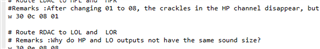
  •  There are notes in the document.

  • Allow me some time to go over your settings

  • Hi Luo,

    Not sure what you mean by sound size.

    HP and LO output drivers are designed for different use cases. HP output is designed to drive headphones with typical impedance of 16-32Ohms driving up to 40mW of power as opposed to LO designed for variety of loads but can exceed 10kOhm driving a 1Vrms signal.

    The ambient noise removal can be due to the slow charging time of the capacitor and Rpop chosen, please review 2.2.3.1 of reference guide again. Also, in register 0x0c there is write to reserved registers

  • Hi Daveon,

    Thanks for your answer, modify Rpop to solve the problem of environmental sound effect output delay.The sound size means that the gain of the ambient stereo played by them under the same AGC parameters is different. The gain of LO is smaller than that of HP.

    And I hope you can reply to my other post that LO does differential output, LO channel does not output the problem of ambient stereo effect, thank you.

    Regards.

  • Hi Luo,

    Okay will do, is this issue resolved?

  • Hi Daveon,

     I also need HP and LO outputs to achieve the same AGC gain effect. What should I do?

  • Hi Luo,

    The AGC is present in the ADC signal chain, so the realized effect is through changes in the PGA gain.. If the INx inputs all have the same input signal level and the AGC gains up the signal to a defined value, each input will have the same result showing in DOUT.

    You can verify this by disabling loopback, and analyzing the audio present at DOUT after recording.

    If the result is different in HPout vs LO, this is due to differences in processing after enabling loopback.