Tool/software:
Hi Team,
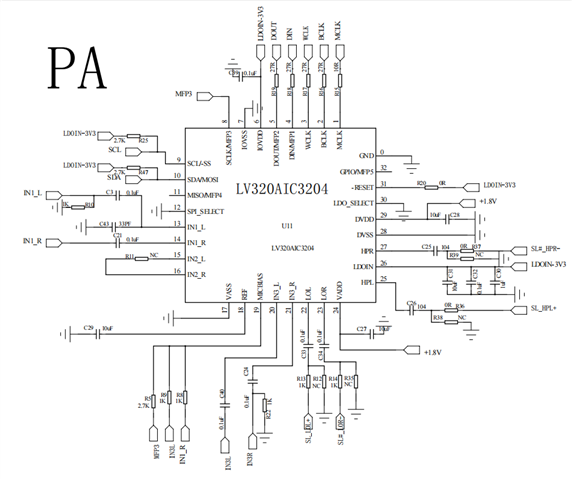
I am using 3204EVM debugging, I want to use IN1 and IN3 to route to LO and HP channels respectively, and achieve stereo effect, I configured their registers, but found that IN1 has no input, and LO has no output, can you help me to see what is the reason, the following is my register configuration:
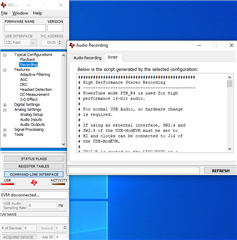
###############################################
# Software Reset
###############################################
#
# Select Page 0
w 30 00 00
#
# Initialize the device through software reset
w 30 01 01
#
###############################################

###############################################
# Clock Settings
# ---------------------------------------------
#The input clock signal : MCLK = 11.2896 MHz,BLCK = 1.4 MHz, WCLK = 44.1 kHz
###############################################
#
# Select Page 0
w 30 00 00
#
# NADC = 1, MADC = 2
w 30 12 81 82
#
# NDAC = 1, MDAC = 2
w 30 0b 81 82
#
###############################################

###############################################
# Signal Processing Settings
###############################################
#
# Select Page 0
# w 30 00 00
#
# Set the ADC Mode to PRB_P1
w 30 3d 01
#
# Set the DAC Mode to PRB_P8
w 30 3c 08
#
###############################################

###############################################
# Enable Loopback Page 0 register 29
###############################################
#
# Loopback enable for stereo audio data

w 30 1D 10
#
###############################################

###############################################
# Initialize Codec
###############################################
#
# Select Page 1
w 30 00 01
#
# Disable weak AVDD in presence of external
# AVDD supply
w 30 01 08
#
# Enable Master Analog Power Control; AVDD LDO is powered down
w 30 02 00

#
# Select ADC PTM_R4
w 30 3d 00
#
# Set the input powerup time to 3.1ms (for ADC)
w 30 47 32
#
# Set the REF charging time to 40ms
w 30 7b 01
#
###############################################

###############################################
#AGC
###############################################
w 30 00 00
w 30 57 7E
w 30 56 F0
w 30 58 44
w 30 59 1A
w 30 5A 08
w 30 5B 18
w 30 5C 06

w 30 5E 7E
w 30 5F F0
w 30 60 44
w 30 61 1A
w 30 62 08
w 30 63 18
w 30 64 06
###############################################

###############################################
# Recording Setup
###############################################
#
# Select Page 1
w 30 00 01
#
# MICBIAS set to 1.7V
w 30 33 50
#
# Route IN3L to LEFT_PGA_P with 10K input impedance
w 30 34 04
# Route IN3R to LEFT_PGA_N with 10K input impedance
w 30 36 04
# Route IN1R to Right_PGA_P with 10K input impedance
w 30 37 40
# Route IN1L to Right_PGA_P with 10K input impedance
w 30 39 10
#
w 30 3b 0c
w 30 3c 0c
#
###############################################

###############################################
# Playback Setup
###############################################
#
# Select Page 1
w 30 00 01
#
# De-pop/Soft stepping
w 30 14 25
#
# Route LDAC to HPL and  HPR
w 30 0c 08 10
# Route RDAC to LOL and  LOR
w 30 0e 10 08
#
# HPL/HPR powered up
w 30 09 3C
#
# Unmute HPL/HPR driver, 0dB Gain
w 30 10 00 00
w 30 12 00 00
#
# Select Page 0
w 30 00 00
#
# DRC
w 30 41 FC FC
w 30 44 73
w 30 45 00
w 30 46 B6
#
# Power up LADC/RADC
w 30 51 c0
#
# Unmute LADC/RADC
w 30 52 00
#
# Power up LDAC/RDAC
w 30 3f d6
#
# Unmute LDAC/RDAC
w 30 40 00
#
###############################################