PCM3168A: 48Khz fs can not generate 256fs BCK in I2S format

Part Number: PCM3168A

Tool/software:

Dears,

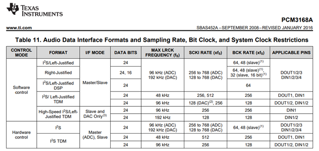
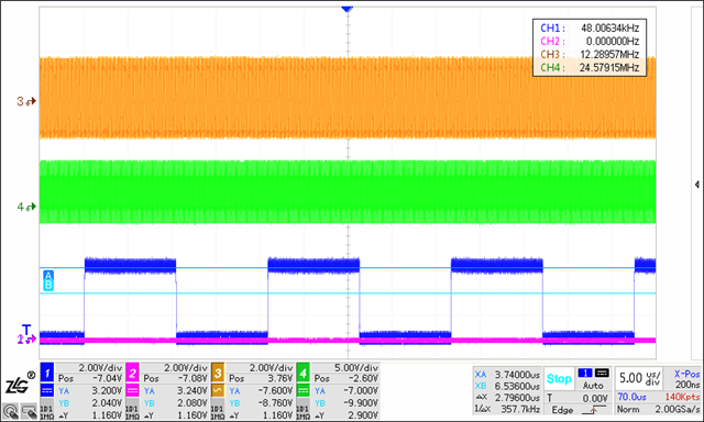
   Customer have an question about BCK frequency

they choose external=24.576MHZ data=32bit 8ch, ADC master, DAC slave, ADC single rate, DAC sample mode Auto, I2C control, normal I2S format no TDM; The output of BCK is 3.072MHZ=64fs;

customer want to BCK 12.288MHZ=256fs;

In I2C control, need fs=192KHZ;

But in hardware control can generate BCK 12.288MHZ when fs=48KHZ;

How to generate BCK=12.288MHZ in normal I2S format no TDM and I2C control mode?

Why the hardware control can generate on these mode?

  • Hi,

    Can you give me some more information about your specific application so we can better assist you?

    For some more information to help answer your questions, the PCM3168A is not capable of using a 192kHz sampling rate for the ADC, it can only support up to 192kHz for the DAC. The codec only supports 24 bits of audio data per word, so 32 bit data will not be supported. 

    To achieve 8 channels of audio at 32 bit and 192kHz sampling rate, you would need a BCK of 8ch * 32bit * 192k = 49.15MHz, which is too large for this device. Instead, you would need to do 8ch * 24bit * 96k = 18.43MHz minimum BCK. On this device, only fixed ratios are supported, so for SCK, 256*fs = 24.58MHz, and similar for a supported BCK rate. 

    Let me know if you have more questions and please send over some more information about your system so that we can help further.

    Regards,
    Mir Jeffres

  • Hello,

       The customer added 8-bit blank data to adapt to the 32-bit data format of the processor, so the data is 32bit, and the actual sampling is 24bit;
    So let me rephrase the customer's doubts
    In hardware control mode, 48Khz fs and BCK can generate 12.88Mhz;
    In I2C control mode, BCK can only output 3.072 MHz, it seems that only 2 channels are enabled;
    Why can hardware control be implemented, but I2C control is not? Do some registers still need to be configured?

  • Hi,

    That sampling of 24 bits seems correct. In the hardware control mode, the speed you are seeing of 12.88MHz is for I2S TDM. You can reach 12.88MHz with I2S TDM with software control as well, look at the "I2S/Left-Justified TDM" row in Table 11. It can go faster with "High-Speed I2S/Left-Justified TDM". TDM stands for time-division multiplexing, and is a way for more than two channels of I2S data to be sent with the same data lines. I2S without TDM can only send two channels at a time, which means that the BCK can be lower as less bits are needed in the same sampling period. You can calculate BCK needed by the sampling rate * number of bits per sample * number of channels. This is 12.88MHz with SR=48kHz, 32 bits (only 24 of which are the actual sample), and 8 channels of audio. The datasheet says the DAC can support 8 channels but the ADC can only support 6. Check out figure 52 in the datasheet to see an example of what the audio data format would look like with 8 channels of I2S TDM data.

    Let me know if you have any more questions.

    Regards,
    Mir

  • Hi,

      Thank you for your feedback
    But the customer believes that in hardware control mode, he set the data format to I2S, not TDM, and measured it with an oscilloscope;
    So there are two doubts:
    1. Is the data format set by the customer as described, not TDM;
    2. If the customer's description is true, why is it that under I2C control, when the data format is I2S, it is impossible to achieve the same results as hardware control;

  • Hi,

    In section 9.4.2 of the datasheet, it says that hardware control mode is selected by the FMT pin (pin 42), low if I2S not TDM, and high if I2S with TDM. Can they check that to make sure their hardware control mode was not TDM? Also, are you measuring the I2S for the ADC or the DAC? 256 bit clock rate is only available for TDM according to the datasheet. You will not be able to achieve 8 channels with just I2S, you would need to use TDM I2S. The software and hardware control options have the same range of clock speeds for I2S without TDM, and the same range for I2S with TDM. 

    Check registers 65 and 81 for ADC and DAC mode selection. 

    Also, are we looking at system clock (SCKI) or bit clock (BCK)? There are a few more ways to get to 12.288 MHz with the system clock than the bit clock, as shown in table 3 section 9.3.4 in the data sheet.

    Regards,
    Mir

  • Hi 

    Customer post the hardware control mode waveform as below, CH1 is fs, CH2 is BCK, CH3 is I2S data.

  • Hi,

    In hardware control mode, 12.288MHz is only possible in the mode called "I2S TDM", which is a way of sending out multiple channels of I2S data in the same line, which is why the clock is faster than a 2-channel I2S output. This is the mode that you seem to currently be in for your hardware control output. Outputting only two channels of I2S per line would allow for a rate 4x slower than outputting 8 channels at once. The BCK rate is 256 * fs for a fs of 48kHz, as shown in Table 11, for "I2S TDM" hardware control mode. In software control mode, you need to use the format "I2S/Left-Justified TDM" to achieve the same 256 * fs rate as you are achieving in hardware control mode.

    If this doesn't help, can you send me your format pins in software control mode so we can confirm what output format you are in?

    Best,
    Mir

  • Hi,

     Customer set "I2S/Left-Justified TMD" mode achieved 12.288Mhz, but there have an new issue, the ovf function disappears.

    registration 0x41 set 0x27,0x51 set 0x07, data format waveform is yellow,

  • Hi,

    Glad to hear that the clock speed is what you desired. I'm not sure how these screenshots show what is wrong with the OVF pin. In section 9.3.8 in the datasheet, it says "The overflow flag is held high for 1024 LRCKAD clock cycles. In parallel, overflow flag information is stored in the OVF bits of the mode control register, and the OVF bit is held until the mode control register is read." Maybe you are checking the overflow flag too late, as 1024 LRCKAD would only be 21.3 ms. Can you check the OVF bits? You will want to read register 86, in Table 28 in the datasheet. 

    Best,
    Mir

  • Hi ,

      Customer has previously verified that when the first channel overflows, the value of register 0x56 in 86 is 0x01. The register seems to detect overflow, but the OVF pin remains unchanged。

  • Hi,

    I have confirmed with one of my colleagues that this is a known bug with the device - when the PCM3168A is in any mode with TDM, the OVF pin does not work as expected and stays low. The OVF register works as expected. We are working on updating the datasheet with this information. 

    Best,
    Mir

  • Hi,

      Thank you! but without hardware flags, using register flags is too slow.

  • Hi,

    Unfortunately, this is a limitation of the device. You can either use I2S only mode, which has a slower audio clock than you want, but you will be able to use the OVF pin, or you can use I2S TDM mode, with the fast audio clock that you desire but the OVF pin does not work. Unfortunately we do not have other devices with the OVF pin feature, if you really need both. I would suggest either figuring out a way to use the register flags in your device or to implement an comparator circuit (this can be analog, so very fast speed) for input clipping detection. Or, you could go back to slower I2S clock speed and use the OVF pin. Sorry about this.

    Best,
    Mir