This thread has been locked.

If you have a related question, please click the "Ask a related question" button in the top right corner. The newly created question will be automatically linked to this question.

PCM6020-Q1: PCM6020-Q1

Part Number: PCM6020-Q1

Tool/software:

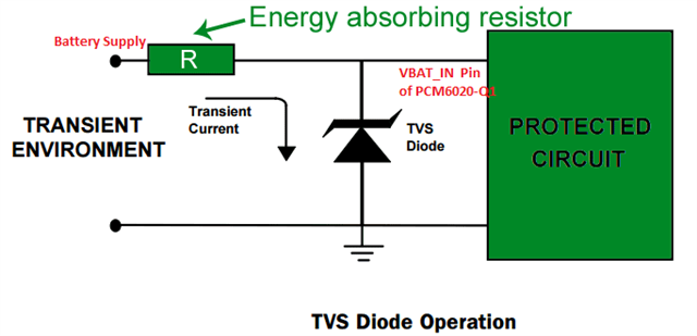
Regarding the VBAT_In query, If we use the step down or voltage divider circuit, how to detect the "input pin short to VBAT_IN or short to battery)?. 

As per PCM6020-Q1 datasheet, A short to VBAT_IN fault occurs when the difference between the voltage measured for the VBAT_IN pin and the
input pin, ABS(VBAT_IN – INxx), is less than the threshold or both the VBAT_IN and INxx pin measured voltages
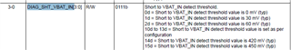
are above 11.7 V. The threshold can be set by configuring DIAG_SHT_VBAT_IN, P0_R101_D3-0.

My understanding is during the short to battery, it will check the configured threshold between VBAT pin to Input pin, if less than the threshold it will detect as short to VBAT. 

Then such scenario, we need to keep VBAT_IN pin as same as battery voltage to detect the short to battery, is my understanding is correct?. 

  • Hi Madhaiyan,

    Your understanding is correct. There are two scenarios.

    1: Direct Battery connection, where the VBAT_IN pin is directly connected to the battery and the VBAT_IN pin reflects the battery voltage. This can be done if the maximum ratings of the VBAT_IN pin are not exceeded. 

    2: Using a voltage divider/ step-down converter to step down the battery voltage to a level that is safe for the VBAT_IN pin. The threshold can be set by configuring DIAG_SHT_VBAT_IN, P0_R101_D3-0.

  • Thanks for your prompt response.

    Option 1 is not possible in our application where VBAT is exposed to the battery transients load dump932V), over voltage(>24V). 

    Option 2 is feasible, we plan to apply regulated 10.5V supply to VBAT_In pin, but i have the following queries to be clarified, 

    i. as per this statement, "short to VBAT_IN fault occurs when the difference between the voltage measured for the VBAT_IN pin and the
    input pin, ABS(VBAT_IN – INxx), is less than the threshold or both the VBAT_IN and INxx pin measured voltages
    are above 11.7 V", let's say Mic Input pin shorted to 13.5V battery, VBAT_In supply is 10.5V, the difference is greater than 450mV and only mic Input pin is greater than 11.7V. it doesn't meet the detection criteria, is my understanding correct?.

    ii. Regulated 10.5V supply to be applied after the ECU completes the bootup, is there any sequence where VBAT_In to be applied first followed by IC AVDD & IOVDD?. 

  • Hi Madhaiyan,

    i). Your understanding is correct. The first condition (difference<threshold) is not met and only one of the voltage levels(INxx) is above 11.7V while the other is below the threshold. Thus, this does not meet the fault detection criteria.

    ii). The VBAT_IN pin powers the diagnostic and monitoring circuits of the PCM6020-Q1, to enable accurate monitoring and fault detection, this pin is recommended to be powered first. Supply power to VBAT_IN will also prevent any latch-up conditions. The power-supply sequence between the IOVDD and AVDD rails can be applied in any order. The customer needs to ensure that the POR voltage (Power-On Reset) is correctly managed during the power-up sequence to avoid any issues related to non-monotonic power supply ramps. Thanks.

    Regards,

    Sam

  • Hi Sam,

    Then for our case, voltage divider/stepdown with different voltage doesn't work, we have to keep the VBAT_IN supply from battery input. 

    Can we use the series resistor to limit the current and TVS diode to clamp the >18V. do you have any example circuit? 

  • Hi Madhaiyan,

    We will review your request and get back to you early next week, many of our engineers are going on holiday this week. Your approach using a series resistor and a TVS diode can work. The reverse stand-off voltage of the TVS diode should be around the normal operating voltage, the clamping voltage should be below the maximum safe voltage for the VBAT_IN pin, and the peak pulse current should be suitable for expected transients. Thanks.

    Regards,

    Sam

  • Hi Madhaiyan,

    Your approach with a resistor and a TVS diode will work. A simple configuration like this will suffice. The TVS diode should be chosen to fit the customer requirements. Thank you.

    Regards,

    Sam