TLV320ADC3120: Bad I2S data

Part Number: TLV320ADC3120

Tool/software:

Hi,

I am trying to get my tlv320adc3120 to work on a breakoout board that I made. I have a condensor mic connected to in1 in differential arrangement, and a second condensor configured asa single ended on in2. The device is outputing i2s with only 0s for ch1, and 363 for ch2. There is no change with sound played. It is connected to an esp32 with i2s configured as master, no master clock output, sample rate 48000, 2 channels, 32 bit word size.

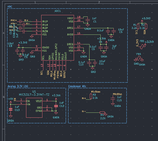
Here is the i2c from my logic analyzer

Start, h9C [ h4E | WR ], h01, h01, Stop

Start, h9C [ h4E | WR ], h02, h81, Stop

Start, h9C [ h4E | WR ], h3C, h00, Stop

Start, h9C [ h4E | WR ], h3D, h54, Stop

Start, h9C [ h4E | WR ], h3E, hC9, Stop

Start, h9C [ h4E | WR ], h3F, h80, Stop

Start, h9C [ h4E | WR ], h40, h00, Stop

Start, h9C [ h4E | WR ], h41, h20, Stop

Start, h9C [ h4E | WR ], h07, h70, Stop

Start, h9C [ h4E | WR ], h08, h00, Stop

Start, h9C [ h4E | WR ], h0B, h00, Stop

Start, h9C [ h4E | WR ], h16, h08, Stop

Start, h9C [ h4E | WR ], h70, hEC, Stop

Start, h9C [ h4E | WR ], h3B, h10, Stop

Start, h9C [ h4E | WR ], h73, hC0, Stop

Start, h9C [ h4E | WR ], h74, hC0, Stop

Start, h9C [ h4E | WR ], h75, hE0, Stop

See the attached schematic for my breakout board.

  • Hi Kagen,

    Can you clarify this statement:  "esp32 with i2s configured as master, no master clock output"

    Do you mean there is no master clock output from the esp32?

    Thanks,
    Jeff McPherson

  • Correct, no master clock output from esp32, it is generating FS and BCLK 

  • Hi Kagen,

    I ran your script on an EVM and found that your channel two slot was misconfigured. By default channel two is the left slot 1 when it should be right slot 0. I've updated the script below. Try that and let me know if anything changes.

    w 9c 01 01
    w 9c 02 81
    w 9c 3c 00
    w 9c 3d 54
    w 9c 3e c9
    w 9c 3f 80
    w 9c 40 00
    w 9c 41 20
    w 9c 07 70
    w 9c 08 00
    w 9c 0b 00
    w 9c 0c 20 #missing, set ch2 to right slot 0
    w 9c 16 08
    w 9c 70 ec
    w 9c 3b 10
    w 9c 73 c0
    w 9c 74 c0
    w 9c 75 e0

    Best regards,
    Jeff McPherson

  • Thanks that got my channel two working, however channel one is still outputting only 363 repeatedly. I have channel 2 connected to a condenser mic that is biased directly from 3.3v, while channel one is biased from mbias. I took a measurement of mbias and is only outputting 1.295V, while Vref is showing 2.7V. 

  • Hi Kagen,

    I got a clean signal on channel 1 in my testing so it's nothing with software.

    I'm not super familiar with your schematic format, but is the Micbias connection after the AC coupling cap i.e. on the same node as the input pin? Mbias should be coupled from the input pin, since the ADC is going to try to provide it's own center voltage for the ADC. Also the cap will absorb Mbias and so the mic won't power on to begin with.

    Best regards,
    Jeff McPherson