This thread has been locked.

If you have a related question, please click the "Ask a related question" button in the top right corner. The newly created question will be automatically linked to this question.

DRV2700EVM-HV500: PiezoControlConsole Test.

Part Number: DRV2700EVM-HV500

Tool/software:

Hi, T.I.

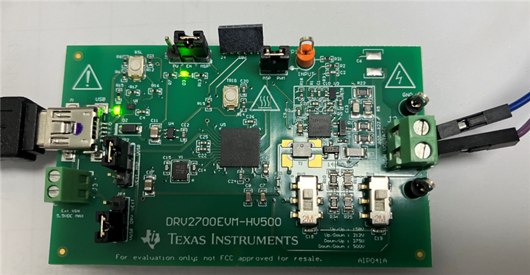
I am testing with DRV2700EVM-HV500.

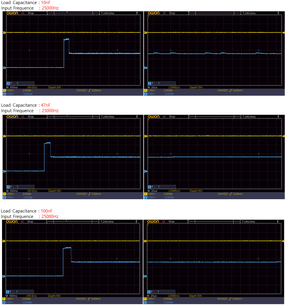
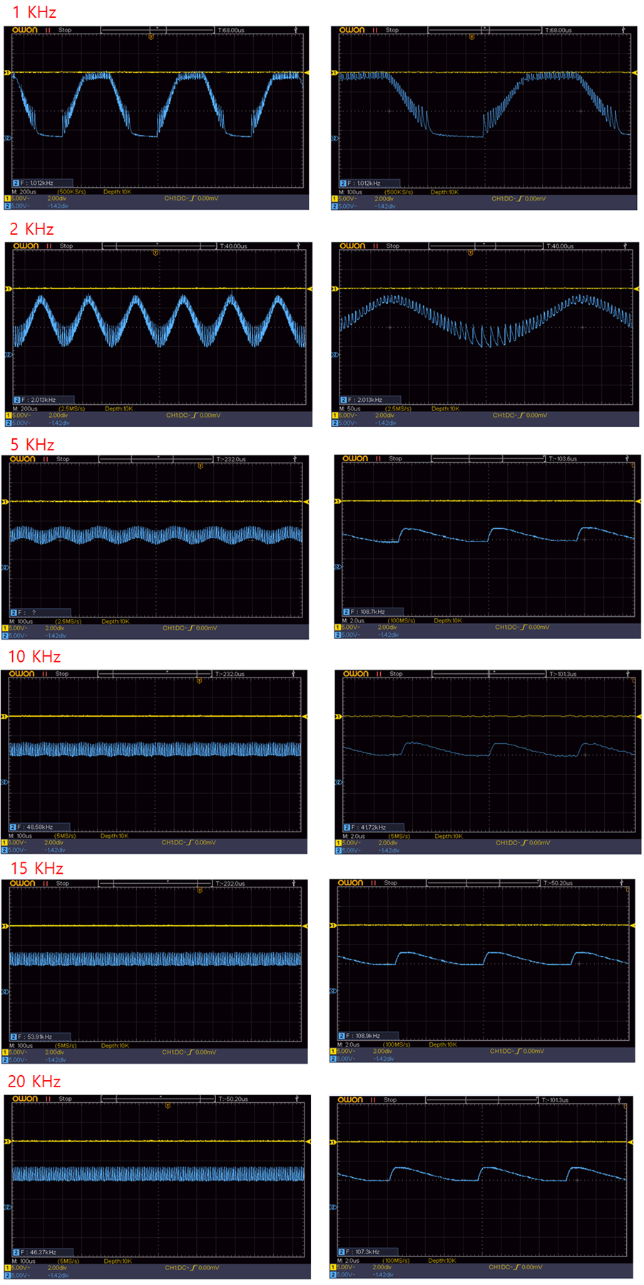
I test by adjusting the PWM Input Frequency, but the expected waveform does not appear.

Waveforms can be distinguished up to 5000Hz, but beyond that, waveforms cannot be distinguished.

Could it be that I made some mistake?

The environment is as follows:
================================================
Target : DRV2700EVM-HV500
Firmware : TI-Haptics-DRV2700EVM-HV500 v1.1
OS : Windows10 Pro x64bit
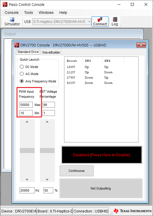
PiezoControlConsole Version : 1.2.9.0
Mode : Any Frequency Mode
================================================

Please refer to the following image for board connection status and oscilloscope waveform.


Thank you in advance.

Regards,
Simon

  • Hi Simon,

    It looks like the input signal is being attenuated. What is your load capacitance? Thanks,

    Regards,

    Sam

  • Hi, Sam.


    Thank you for your answer.

    I would like to check the output waveform of 24000Hz.
    But I don't get the output waveform I expected.

    What load capacitance should be applied to obtain an output waveform of 24000Hz?

    I tested load capacitances of 10nF, 47nF, and 100nF and a frequency of 25000Hz, respectively.

    Regards,
    Simon

  • Hi Simon,

    This device has a 200V peak to peak amplifier and is capable of driving up to 500V. I see that you are only using a 10V input, you should consider using a different device. This device is mainly used if the customer wants to drive hundreds of volts and cannot drive high frequencies. Furthermore, the EVM has a first order filter, the RC network has a 3-dB point at 1.75kHz. If you want to increase the 3-dB point you can adjust the filter, but the 3-dB point cannot be any higher than 5kHz. Please see section 7 of the EVM guide for more information. Thanks.

    Regards,

    Sam

  • Hi, Sam.


    Thank you for your answer.

    The voltage of the oscilloscope you mentioned is an attenuated (x10) voltage, and the actual applied voltage is 158V.

    This is a waveform measured by connecting only the load capacitance without any modification.

    The waveform shows 0V -> 158V -> approximately 80V.

    The load capacitance appears to determine how long it stays at 158V after startup.

    Is it not possible to observe the waveform at 25KHz?


    Regards,
    Simon

  • Hi Simon,

    Unfortunately, at such a high PWM frequency (above 20kHz), the PWM signal will be greatly attenuated. This is why the signal appears to look like DC after the input filter. Thanks.

    Regards,

    Sam

  • Hi, Sam.


    I am very sorry for asking you such a troublesome question again.

    As shown below, the Piezo Control Consol displays the PWM Input Frequency supported by DRV2700EVM-H500 as 10~50000 Hz.

    What is the range of PWM Input Frequency actually supported by the DRV2700EVM-H500?

    Do I need to configure an additional circuit to obtain an output waveform of 20KHz or higher?

    Regards,
    Simon

  • Hi Simon,

    This device supports frequency up to around 20kHz. With a low PWM frequency (<1kHz) majority of the signal will propagate through and will be a square wave. Mid PWM frequency (1kHz to 20kHz), the output will somewhat reflect the signal, but will depend on the load capacitance. Anything above this will be greatly attenuated will the signal may appear to be DC. Thus, this mode can be used to drive the output at a DC level. The 50kHz max frequency setting you see is the DC Mode- Quick Launch frequency button. This mode is used to drive the output at a DC level which is set by the duty cycle. Thanks.

    Regards,

    Sam