TAC5212: "Configure PLL" settings in PPC3, guide and reference material for divider names

Part Number: TAC5212

Tool/software:

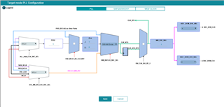
In PurePath Console 3 in the TAC5x1x-Q1 app with theTAC5212 selected, in the "Audio Serial Bus" tab under "Primary ASI Format Configuration" there is a button "Configure PLL" that opens three block diagrams GUI's that alloy you to set the PLL and clock dividers for the CODEC. Is there a guide on how to use set up the clock dividers, and is there reference material that explains what all of the divider acronyms mean.

I am trying to set up the TAC5212 to have MCLK in and it's internal PLL off, with the clock dividers set up manually. I have used the AIC3206 in the past and all the information on how to set up the clock dividers is in the application reference guide. The TAC5212 data sheet does not have information of how to manually setup the clock dividers. I am interested in having the lowest power possible while having stereo ADC for a battery operated application, so I want the PLL off to save power, if there are any premade setups in PPC3 I can try please point me to them, and/or guide material on how to set up the clock dividers.

  • Hi Avery,

    Since the device isn't fully released yet, we don't have published info on the PLL to the same detail like we do in the AIC3206 yet.

    We do have this app note that explains some of the automatic clocking configurations: https://www.ti.com/lit/an/slaaeg6/slaaeg6.pdf?ts=1721767933032&ref_url=https%253A%252F%252Fwww.ti.com%252Fproduct%252FTAC5212

    The PLL will be auto enabled if necessary. You can check if the PLL is on by checking register 0x3E.

    Best regards,
    Jeff McPherson

  • Thank you, I have seen that guide, it is helpful yet does not explain how to set up the clock dividers manually past saying "User Configures all the Dividers manually in this mode". PPC3 has the block diagram that looks like it would be very useful, but without the information on how to set up the dividers for the system to work it isn't useful. 

    I am finding it difficult to make functional setups for the TAC5212 using PPC3. PPC3 will dump register data for registers in pages over the three pages in the TAC5212 which is confusing. I have been attempting to set up two TAC5212's on the same TDM interface in PPC3 and export the registers with the 'dump to output window', it recently incorrectly set the Clock configuration registers to set the ASI sample rate to maximum when PPC3 was set to auto detect.

    Is there a library of .pcc3 files for the TAC5212?

  • Hi Avery,

    Sorry to hear that it's not going well. To clarify, there is a separate register map feature that lets you view the register map with labels. This is different than the register dump feature and can be found on the left side of the screen.

    We don't have a library of PPC3 files. A reminder that this device has not been fully released and PPC3 is still under development, so your feedback is appreciated and needed.

    It sounds like you want to configure two TAC5212's as a daisy chain. What's your goal with the PLL configuration? Is there a particular clock input/output sample rate you are aiming for?

    Best regards,
    Jeff McPherson

  • Hi Avery,

    We're working to change the export script format to be more user-friendly. Also, when configuring the device to operate on a shared TDM bus, just ensure that the data slots on each device do not conflict with each other. 

    The only 'PPC Libraries' available are the preset configurations you can load at the top right hand of PPC3.

  • I will just wait till there is better documentation on custom clock and divider settings for the TAC5212.