TAS6422-Q1: Frequence Response

Part Number: TAS6422-Q1

Tool/software:

Hi support Team, 

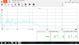
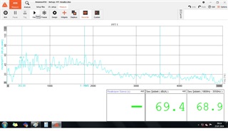
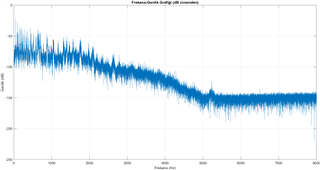
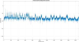
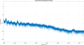
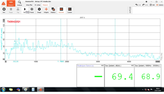
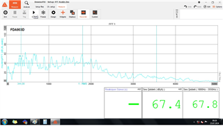
When we measure the FFT graph of the ECU, the frequency spectrum after 3000 Hz is not as expected. We are trying to identify the correct FFT graph by comparing the ECU used with another amplifier (FDA903D) under the same environment and conditions. The WAV file being played is the same: 16-bit, 44.1k sample rate. The only difference between the ECUs is the amplifier units. The TAS amplifier's configuration settings are all at their default settings, and when I checked all the register fields, I did not see any settings related to this issue. There is a High Pass Filter and corner frequency setting, but since they are 4, 8, 15 Hz, I considered them irrelevant.

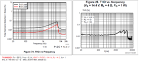
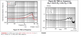
We compared the Frequency THD vs. frequency graphs of the two amplifiers. (RL=4 ohms for both ECUs.) I did not see any significant difference. In fact, the THD rate in the frequency band of the TAS amplifier looks better There were some differences in the THD vs. output power graphs. However, I increased the input voltage of the ECU with the TAS amplifier from 12V to 15V ( and so icreases the VDD pin of the amplifer) and did not see a significant difference in the FFT after 3000 Hz. There were some differences in certain frequency bands, but this is not the main cause.

The amplifier outputs of both ECUs are designed according to the filter circuits specified in their own datasheets or the Evaluation Boards. What is the main cause of this diffrence? Which point should I focus?


  • Hello,

    I can see a difference in level above 3kHoz on the FFT between the two graphs.  Which graph is the TAS6422-Q1 device?  I cannot comment on the competitive device as I am not familiar with its internal operation. What are your expectations?  Also, what is your end product and what is the significance of the 3kHz and above signal for your end product?

    Regards,
    Gregg Scott

  • Hello,

    We could plotted the audio file(wav) in frequence spectrum in Mathlab. So the expected measurement is as below (ignore magnitude of the amplitude value): 


    The measurement of the ECUs are below which has TAS and FDA Amplifier respectively:


    Datasheet Comparing :

  • Goknur,

    I still do not understand the question?  Do you expect to see a sound intensity of 69.4 or 67.4?  What are you trying to determine or prove with your measurement?  You seem to see a higher output on the TAS6422E above 3kHz.  It could be that the filter has some rise in the higher frequencies due to variations.  Are you connected to a speaker load or a resistor load?    Speaker loads will interact differently with the LC filter.

    You can use sine waves and see if it is due to THD or Filter reactions.  Using a dynamic audio signal can mask things.

    Regards,
    Gregg Scott

  • Hi,

    Do you expect to see a sound intensity of 69.4 or 67.4? 

    No. I do not care the amplitude(dB) of the sound. We can set and calibrate it easily.

    Are you connected to a speaker load or a resistor load?

    Connected and used only speaker load. 

    The interesting  point and What I couldn't understand, characteristic of the sound is diffrerent from the graphs in MATLAB above 3 kHz .So we can hear the difference acustically. When we examine the FFT of the sound and compare them, I find the FFT measurement graph of the ECU with FDA more closer to the graphs in MATLAB.  Why? Maybe the FFT of the TAS is correct but I can't sure that teorically. My expectation is to understand this difference and achieve the correct FFT graph. I want to ensure that I play the sound correctly. 

    Beside, What is the bit field SDM_OSR (OverSampling Rate) in Miscellaneous Control 2 Register [0x02]. How does it affect to the sound or signal?

  • We have solved it. There is a  difference i2s part in the software. FFT's are similar each other now. 

    But still I couldn't understand what exactly SDM_OSR was.  

    Thanks.