Tool/software:
Hello everyone,
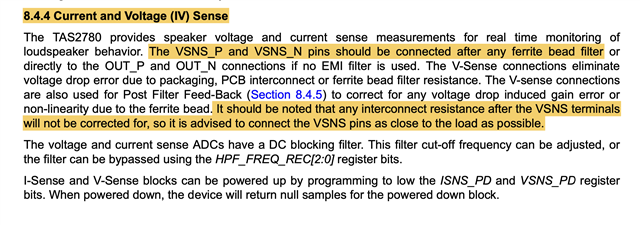
I'm a little confused by the VSENSE ISENSE information in the data sheet for the TAS2780, it seems to imply that any additional resistance (or other parasitics) on the VSNSN or VSNSP lines will not be corrected for in the post filter feedback. (see page 27),
Then in the Electrical Characteristics section Ros (OUT to VSNS resistors with load disconnected) recommended value is 10k (see page 5),
![]()
In this related question the recommended value is 4.7k, this value comes from a screenshot in a data sheet that might be old because I cannot find it.
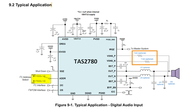
In the TAS2780 data sheet the values in the example are 1k (see page 81).
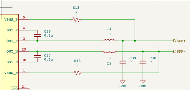
Here is the schematic I am working with. I am yet to define the LC filter values, but you can see I have bootstrap capacitors C36 and C37 connecting BST to OUT and R12 and R13 are VSNS resistors.
Can anyone comment on,
- sensible values of R12 and R13?
- values and location of C36 and C337, are they connected in the correct place?
- Recommended LC filter values using the TAS2780?