DRV595: Maximum Slew rate for SDZ pin

Part Number: DRV595

Tool/software:

Hi all,

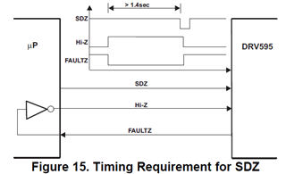
According to the absolute maximum rating of the data sheet, maximum Slew Rate of SDZ  is 10V/ms.
In addition, the note (2) which seems to be due to current restrictions is written as follows;

    100 KΩ Series Resistor is Needed if Maximum Slew Rate is Exceded.

What is the reason why MAXMUM SLEW RATE is restricted?

Is it necessary to protect this through rate when controlling SDZ directly with a CPU?
In this case, is it necessary to have a 100k ohm in series resistance?
When the power is launched, the SDZ is fixed to LOW.

Regards,
Toshi

  • Hi Toshi,

    The limitation in slew rate may come from the fact that faster slew rate means higher di/dt which device may not support (note that this pin could be shorted to PVCC). Adding high impedance resistor such as 100kΩ would help limiting the current.
    It should be OK to start the operation with SDz pin pull-down.

    Best regards,
    -Ivan Salazar
    Applications Engineer

  • Hi Ivan-san,

    Thank you for your reply.

    Please tell me a little more about the slew rate specifications.

    When trying to control SDZ with a CPU or other device like FPGA, the specification of 10/ms (max) seems like a very slow value.

    1. When controlling with a CPU or other device, is it necessary to insert a resistor in series to limit the current?

    2. If a resistor is not inserted in series with the SDZ control line, is there a possibility that logical problems will occur in the SDZ functions? 

    3. What value would be appropriate in this case?

        As a reference connection, we use the case of Figure 15. Timing Requirement for SDZ.


    4. It seems that the pins FS0, FS1, FS2, HI-Z, SDZ, and MODSEL related to the control of the DRV595 are designed to depend on the power supply voltage of PVCC or AVCC. Is that correct?

    Therefore, when performing these settings on H/W, I think it is necessary to consider what is written in E2E below, and be careful about the slew rate.

    "For FAULT pin, a pull-up resistor is recommended to limit the slew rate of the voltage which is presented to the pin during power up. Depending on the output impedance of the supply, and the capacitance connected to the power net on the board, slew rates of this node could be high enough to trigger the integrated ESD protection circuitry at high current levels, causing damage to the device. supply.”

    Reference E2E URL: https://e2e.ti.com/support/motor-drivers-group/motor-drivers/f/motor-drivers-forum/583612/drv595-faultz-pin-behaviour/2143493

    Thanks and regards,
    Toshi

  • Consider slew rate limitations if you're connecting the pin to PVCC. Otherwise, the voltage is lower and the current constraint doesn't apply, so the slew rate can be slower for lower voltages like that from a CPU or FPGA.

    Best regards,
    -Ivan Salazar
    Applications Engineer

  • Hi Ivan-san,

    Thank you for your answer.

    I'd like to ask a more specific question.

    From the observed waveform, the tr/tf of the signal from the actual CPU to SDZ is on the order of several tens of ns, which is much larger than the maximum specified slew rate value of 10V/ms.
    In a case like this, is it possible that an error will occur in the logical function of SDZ?
    For example, is it possible that the shutdown will not be released even if SDZ is changed from low to high to release it?

    If there is a possibility that an error will occur, what specific measures are necessary?

    The background to the question is that when performing a power-on test, in very rare cases there is no output from the DRV595.
    The DRV595 operates normally when the power is turned off and then turned on again.
    The rated output of the DRV595 is set to about 350mA.

    I would appreciate your advice.

    Thanks and regards,
    Toshi

  • Hi Toshi,

    So, to summarize, the slew rate you have on SDz pin is faster than the spec, correct?
    That in addition to the explanation of the ESD protection, may explain why in some cases the device can't come out of SDz. It may happen that the device triggers ESD protection and thus not enabling until the SDz is latched again.

    I would think a resistor value of 10k-100k Ohm would be good to limit the edge rate in this case. Have you tried any resistor at all so far?

    Best regards,
    -Ivan Salazar
    Applications Engineer

  • Hi Ivan-san,

    Thank you for your answerand  advice.

    Yes, the slew rate on SDz pin is faster than the spec.
    I will ask our customer to try inserting the resistor you recommended between the CPU and the SDZ pin.

    Thanks and regards,
    Toshi