Tool/software:
Good morning
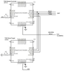
What is the way to connect the I2S signals of two TAA5242 chips in TDM4 master (controller mode).
I can't find the schematic in the data sheet, there is only Fig6.2 for target mode.
My guess is that the first chip connected to the DSP operates in master mode (CH1/2), the second in slave mode (CH3/4) and provides data to the first chip through the MD6 pin
MCLK is connected only to MD3 of the first chip.
LRCK/BLCK signals are probably connected between the chips, but I would like to confirm this.
Greetings
Hi Adam,
Figure 6-2 is the correct one. Daisy chaining is only possible on a target device and only one TAA5242 device can be the controller device. This controller device will generate FSYCN and BCLK outputs, as well as CH3 and CH4 data. The I2S clocks (no MCLK) are given to the target / daisy chained device through the respective FSYNC and BCLK pins. The CH3 and CH4 data are delivered to MD6. The target device then places all 4 channels on the DOUT channel.
Best regards,
Jeff McPherson
Hi Adam,
MD6 and DOUT are flipped. The DOUT from the controller device should connect to MD6 of the target device. Everything else is correct.
Best regards,
Jeff McPherson
So the connection as in the revised diagram?
TDM4 out to DSP from slave/target circuit.