This thread has been locked.

If you have a related question, please click the "Ask a related question" button in the top right corner. The newly created question will be automatically linked to this question.

Dual-rail supply design for a DRV134 balanced line driver

Other Parts Discussed in Thread: DRV134, DCH010515D

Hi all

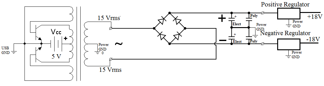
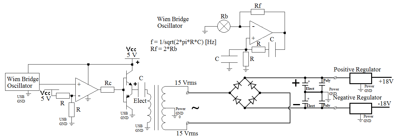
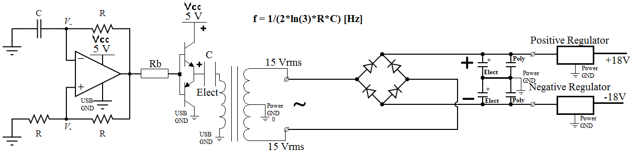
I'm involved in the design of some fairly high-end audio equipment for which we need to include a balanced audio line output; I'm looking to use the DRV134, but was hoping someone with more experience than me (i.e. probably most of you!) could give their opinion on the best (in terms of performance rather than cost/efficiency) way of deriving a +/-18V supply from a single 5V rail (the device in question will be USB-powered).

Parts cost is less of an issue than audio performance, but unfortunately my limited background in audio design means I don't know if there's a generally accepted way of doing this well!

Many thanks

Angus

  • Hello Angus,

    The only way that I know to convert 5VDC to +/-18V is the same used in car audio high power amplifiers, you need an inverter to convert your DC supply current into AC at the desired voltage then you can use either an SMPS or a linear power supply (consisting of a bridge rectifier, supply filtering capacitors and a linear regulator).

    The linear power supply will give you better results.

    The problem is that I unfortunately don't know much about inverters, so I don't know if that design works (design attached) :(

    I don't know how to calculate the frequency of the AC line, unfortunately :(

    Thank you very much for your attention,

    Best regards,

    Daniel Almeida

  • Hello everyone,

    Some power inverter schematics, but I've the same problem I'm not sure if they work,

    Thanks you very much for atention,

    Best Regards,

    Daniel Almeida

  • All

    have a look at the integrated dual low power inverter: http://www.ti.com/lit/ds/symlink/dch010515d.pdf

    rgds,

    K N Madsen

  • Hello Eng. Kim Madsen,

    dch010515d seems an interesting dual low power inverter, but you still have to use filter capacitors after the full wave rectifier and two regulators to improve ripple rejection, I'm I right?

    Some of the circuits I posted works?
    If so they have a poor eficiency, am I right ?

    I found this area interesting so as a student of electronical engineering, I tried to design some based on the principle behind power inverters.

    This inverter is electronically switched right?

    What is the the type of wave that enter in the transformer windings, it's a square wave?

    The transformer and rectifier is included in the device, right?

    If so the transformer included is toroidal?

    Seems very interesting.

    Thank you very much for your help,

    Best regards,

    Daniel Almeida

  • Hi,

    what I use is a boost dual-output inverting switcher -its not an Ti product, but looks similar to a Dual of  the TPS61170-

    In my case it generates +-15V from a single +12V supply, but it could also be designed for a single +5V supply.

    The output voltages are then post-filtered with linear lownoise LDOs. Right at the POL a discrete Gyrator guarantees low output impedance, low noise and clean supplies.

    The circuit supplies a discrete IV-converter stage with hardly any PSRR. So the requirements regarding power supply noise and stability is high.

    Still though dead silent audio output and small PCB-footprint.

    It´s a non-isolated design, that doesn´t utilize  transformers but inductances and Diodes.

    regards

    Chris