This thread has been locked.

If you have a related question, please click the "Ask a related question" button in the top right corner. The newly created question will be automatically linked to this question.

TAS5707 PLL autolock error

Other Parts Discussed in Thread: TAS5707

I am debuging new design with TAS5707 + ARM M4 + MEMS microphone.

I cannot get any sound from TAS5707.

I am running on fs=16kHz, BCLK=768kHz  MCLK=6,144MHz

I am using MCU crystal which is 8MHz so the master clock is generated internaly by dividing and droping cpu clocks - so there is some jitter.

How much is TAS5707 tollerant to MCLK jitter?

When I read register 0x00 I get 0b10010000 so I suppose that TAS5707 detect my setup Fs=16kHz and MCLK =384xFs correctly

Then when I read error status register I get autolock error bit . What this bit means?

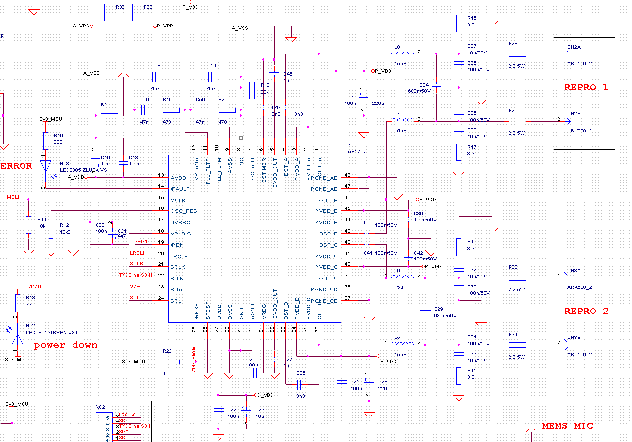
My design is based on TI EVM module schematic.

When I scope MCLK it looks little "nervous". When I scope audio power outputs there is zero signal.

Regards

Luke

  • I read a lot about users experience with TAS devices on this Forum.

    I know that I must clear error register but there is autolock error again.

  • Hi, Lukas,

    Yes, e2e is a great reference!!!

    I have asked my colleague to look into your specific situation.

    -d2

  • Lukas,

    The I2S clock rates you mentioned are not valid for the device.

    -- SCLK should either be 32*Fs or 64*Fs 

    --The supported MCLK rates are also shown in data-sheet (Register 0x00 description section).

    With valid clock rates/ratio's the clock error issues you reported should be fixed.

    -Ravi

  • Thanks for reply.

    I made corrections in MCU registers to pass TAS5707 requirements.

    Now I have Fs=16kHz (real value 160010Hz), SCLK=512kHz (real value 510.1 - 513.2kHz), MCLK=6.144MHz ( real value 5.882-6.270MHz)

    The autolock error is still present.

    My sw startup:

    AMP_PDN_NORMAL; //NO PDN 

    AMP_RESET;               //TAS5707 RESET

    delay();                         //200ms

    AMP_NORMAL;          //TAS5707 normal operation

    delay();                        //200ms

    I2C_WriteRegister(0x1B,0x00);   //trim osc

    delay();                        //120ms

    I2C_WriteRegister(0x07,0x30);

    delay();  

    I2C_WriteRegister(0x05,0x00);

    delay();  

    I2C_WriteRegister(0x06,0x00);
    I2C_WriteRegister(0x02,0x00);

    I order new XTAL for MCU to pass I2S frequencies more accurately

    Lukas

  • I have still autolock error.

    When I read register 0x1B there is 0b11000000 so the trim was done O.K.

    Are there some measurable waveforms on some TAS5707 pins for determination if there is no problem with external components?

    I dont have in my design a throu-holed area under TAS5707 cooling plate as is done on EVM board  (I am running with 12 OHM load). I dont have this cooling plate connected to any potential (I dont noticed any instruction for this plate in datasheet).

    Any idea where is problem?

  • Today I was successful there was problem with cold soldering on some pin - now TAS5707 works.

    Thanks for support

    Lukas