This thread has been locked.
If you have a related question, please click the "Ask a related question" button in the top right corner. The newly created question will be automatically linked to this question.
Hi,
Could you please describe the recommended power on/off sequence and procedure of the register access for TAS5538?
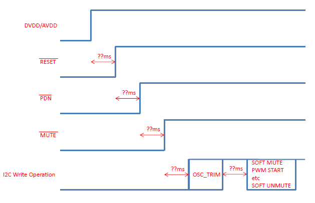
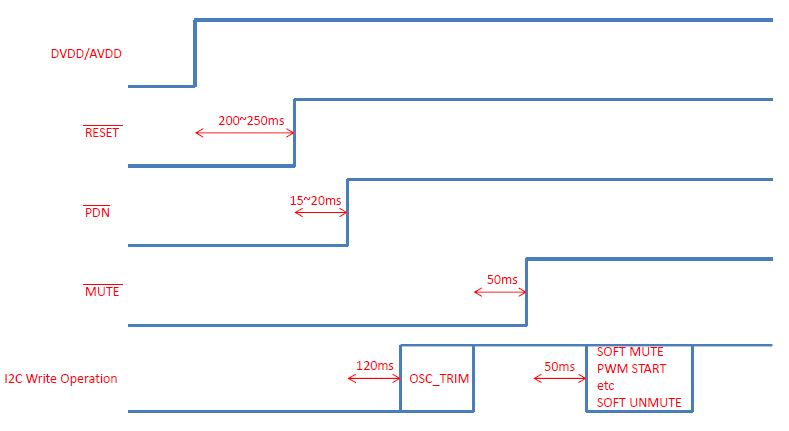
I would like to obtain the information like the timing chart that is described on page 30 to 31 of TAS5731 data sheet.
In addition, could please add the behaviors of RESET, PDN and MUTE pins and the procedure of the register access to the timing chart(soft mute, pwm start, soft unmute, etc.)?
Best Regards,
Kato
Hello Kato-san:
TAS5538 is a stand-alone modulator (no amplifier). TAS5731 is an integrated class-D amplifier with built-in modulator. These two devices are different and thus they have different settings.
RESET, PDN and MUTE are asynchronous. However, VALID is synchronous with RESET and PDN assertion/de-assertion. One normally, de-assert RESET then de-assert VALID, then de-assert MUTE (unmute). VALID should be connected to power-stage (class-D) enable pin. Valid is asserted high.
The settings of these registers must be tested on the system. I would suggest the customer leave them in default settings and adjusted accordingly. Normally, default settings are optimized but in some cases, they need to be adjusted.
Best regards,
Tuan
Oh, sorry, one more piece of information ... PDN is used to conserve power. When PDN is asserted, all register settings are preserved. RESET resets all registers to default settings.
Best regards,
Tuan
Hi Tuan-san,
Thank you for your quick reply.
I will use TAS5624A as the power-stage, connect the VALID pin of TAS5538 to RESET pin of TAS5624A.
Then, should I finish to set all registers before the VALID pin becomes high?
In addition, I show the timing chart of the power on sequence as below, could you please give me your advice regarding the power on/off sequence in detail when using TAS5538 and TAS5624A?
Best Regards,
Kato
Hi Kato-san:
As mentioned in previous post, TAS57xx is not the same as TAS5538 and shouldn't be used as guidelines. The diagram above was extracted from TAS57xx.
Yes, it would
The settings below are suggested settings and are extrapolated from pages 57 and 58.
~200-250mS from power good to RESET de-assertion (high)
~15-20mS from RESET de-assertion to PDN de-assertion
~120mS from PDN de-assertion to MUTE de-assertion
~I2C commands can be written while MUTE is asserted. It would be safe to either write I2C while MUTE is asserted or wait ~50mS @ 48kHz Fs (default setting) after MUTE is de-asserted before writing I2C commands.
Best regards,
Tuan
Hi Kato-san:
During automatic bank switching, the mute is automatically generated and the system does not need to handle mute pin.
Best regards,
Tuan