
- Ask a related questionWhat is a related question?A related question is a question created from another question. When the related question is created, it will be automatically linked to the original question.
My Senior Thesis group and myself are attempting to configure my PCM1863 over SPI using the ESP8266 microcontroller. We have tried viewing the results over I2S and have gotten none when using a logic analyzer. I have attempted read operations and gotten no data back. It would be very appreciated if someone is able to review my hardware schematic and code to point out any oversights.
We are programming it by sending 16 bits, with the most significant 7 being the register, the 8th bit being the read/write bit, and the least significant 8 being the value to send to the register.
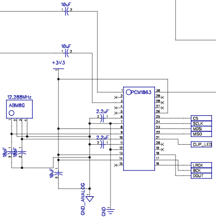
Our schematic is as follows:
We are using a 3.3V supply, ground, and a 12.288MHz crystal for the clock.
The C code for setting up the ADC is as follows:
ADC_cmd(0x20, 0x11); //set ADC as master, auto clock detect, Xtal
ADC_cmd(0x23, 0x02); //set clock divider to 1/3, 12.288MHz/3 = 4.096MHz
ADC_cmd(0x00, 0x00); //select page 0
ADC_cmd(0x01, 0x0C); //0001100_0 for CH1L +12dB
ADC_cmd(0x03, 0x0C); //0001100_0 for CH2L +12dB
ADC_cmd(0x05, 0xBF); //10111111
//RSV default 1
//ADC Channel 1 Input Select Left, only choice for the used pins
ADC_cmd(0x06, 0x50); //0X01_0000 VIN1P, VIN1M DIFF
ADC_cmd(0x07, 0x40); //no select 01000000
//ADC Channel 2 Input Select Right, only choice for the used pin
ADC_cmd(0x08, 0x40); //no select
//RSV default 1
ADC_cmd(0x09, 0x44); //0X000100 VINR3 SE
//register 0x0A stays default
//receive 16 bit depth, LRCK duty cycle 50%, stereo PCM 16 bit,I2S
//RSV default 1
ADC_cmd(0x0B, 0xCC); //110 01100
ADC_cmd(0x12, 0x44); //01000100
ADC_cmd(0x20, 0x91);
Any insight into our problem would be greatly appreciated, as we have reached the final months before the project deadline.


