Hi Team,
The customer is using TAS5717EVM.
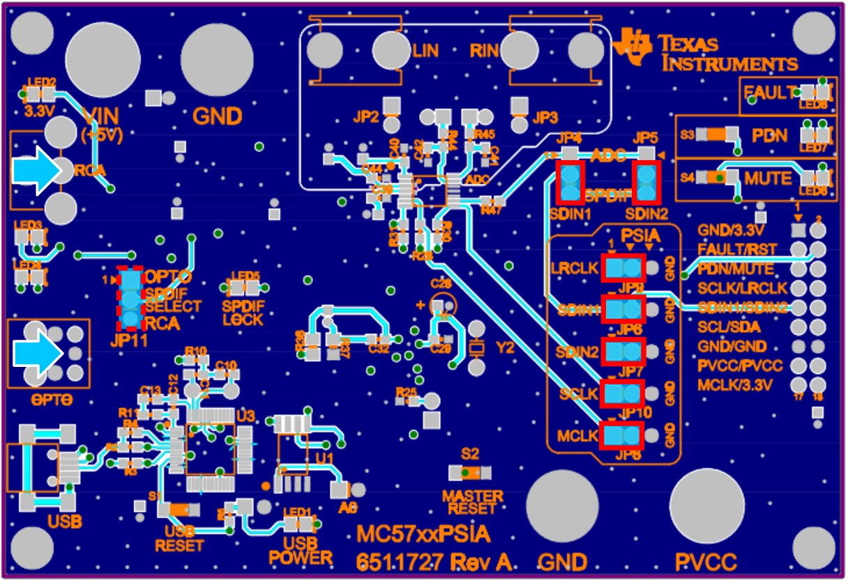
Hardware settings: JP4 and JP5 are cutovered ADC input. That is the 1pin to the 2pin can be connected for JP4 and JP5.
JP11 is cutovered RCA input. Others are default. The customer uses a 4ohm 5W speaker.
Then the customer installs the GUI software.
Software settings: 1. Changing Windows Environment Variables---PPSI2C is 54. Use the I2C memory tool to read 0x00 address, and the return value is 6C.
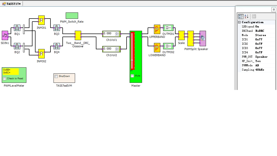
The GUI software are settings in the attachment . Then the customer uses as the ADC Analog input signal and select the speaker output on the GUI software.
Then there is not any sound for the speaker.
But if the customer uses the headphone output and connects the 1pin to the 2pin for JP1 and JP2. The headphone has the sound. And the Shutdown that is on the GUI software is fine, but the Mute that is on the GUI software is not fine. That is the headphone cannot be muted.
Q1: Is there any setting error for the customer? How to set the EVM board and the GUI software to make the speaker have the sound when the customer select
the ADC Analog input signal? I think the 1pin and the 2pin for JP6 and JP7 can be connected.
Q2: The customer would like to use their company‘s I2S signal on the EVM board. The MCLK signal frequency is 12.28MHZ. The LRSLK signal frequency is
48KHZ. The SCLK signal frequency is 1.536MHZ. The I2S is set 16 bit. Then the customer connects the MCLK、LRCLK、SCLK and SDIN signal lines to the
EVM board, but there is no any sound for the speaker.
How does the customer do if the customer would like to use their company‘s I2S signal on the EVM board and select the speaker output?
Best Wishes,
Mickey Zhang
Asia Customer Support Center
Texas Instruments