This thread has been locked.

If you have a related question, please click the "Ask a related question" button in the top right corner. The newly created question will be automatically linked to this question.

TAS5719EVM: No SPDIF Lock Indicator Light

Part Number: TAS5719EVM
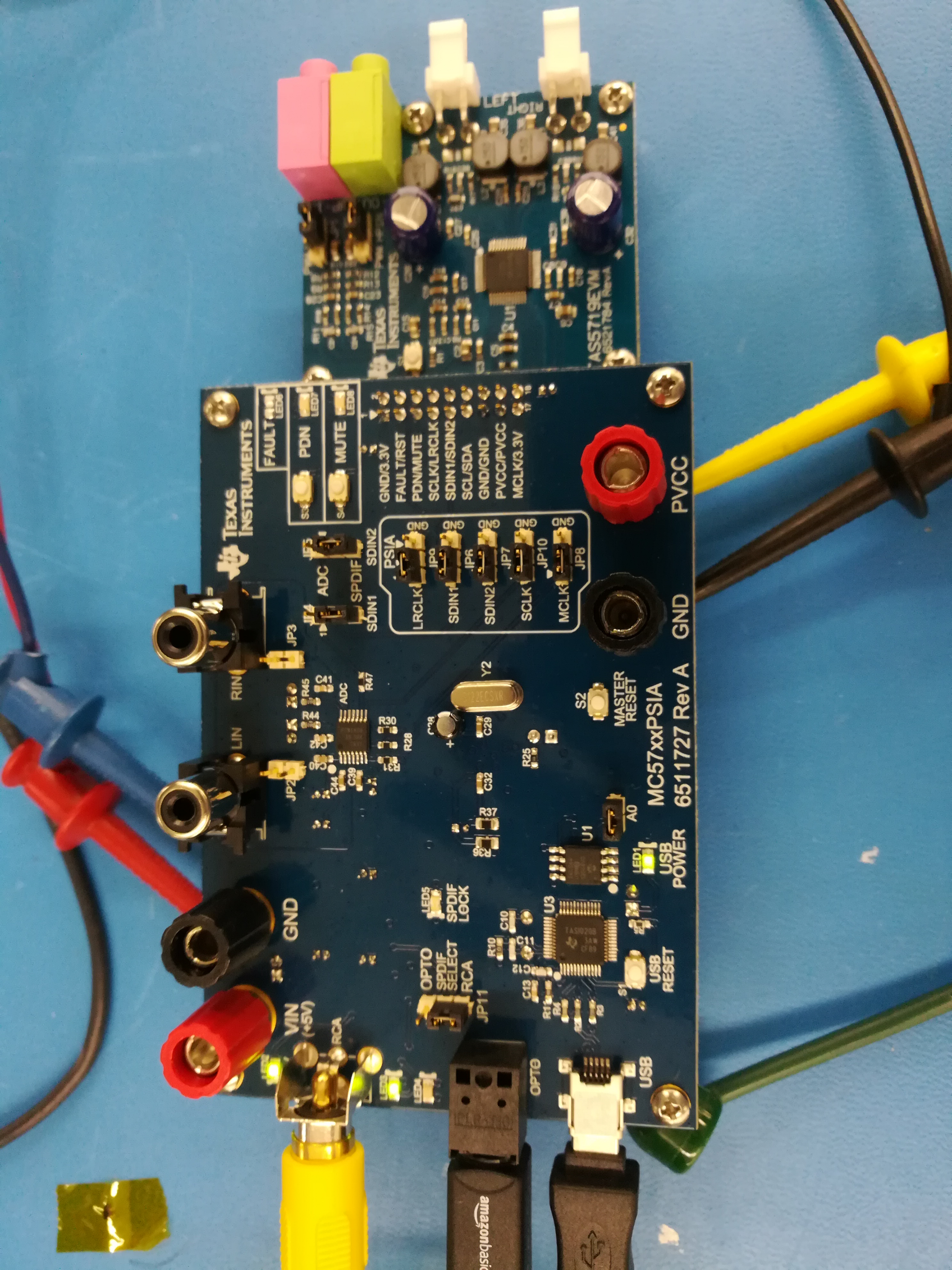
Other Parts Discussed in Thread: TAS5717EVM, TAS5719

I just received the TAS5719EVM eval board.  I have tried to input both optical and RCA digital inputs into the board and the sync light does not come on, and therefore no audio on the output speaker.  I am powering the board with 5V for the digital supply and 12V for the analog supply.  I have also tried the analog audio input, but that does not seem to work either.  Please advise.

  • Hello Brandon! Are you working in Windows, and do you also have the Setting TAS5717EVM/TAS5719EVM Environment Variables document to reference: www.ti.com/.../slaa482.pdf ? This is in addition to the User Guide. Thanks, Jeff
  • Hi Jeff,  I am running windows and have set up the environmental variables as described in the instructions.  However, when I do a read, it comes back 00 instead of 6C.  It seems that everything connected properly.

    Thanks, Brandon

  • Hello Brandon!

    Once everything is set up, is the GUI still open? Please note per the below that if the GUI is still open, you need to close it and then reopen to get the right setting.

    Section 3: Testing I2C Communication: Once the environment variables have been confirmed, you need to test the system for successful I2C
    communication. To do this, follow these procedures.

    1. Connect a USB cable from the MC57xxPSIA (attached to the TAS5717EVM or TAS5719EVM) to your PC.
    2. If the TAS57x GUI software is already open on your system, close it; the environment variable settings change does not take effect until the software is closed.
    3. Start the TAS57x GUI software.
    4. Navigate to Tools, then select I2C Memory Tool. Select the I2C tab.
    5. Read the I2C subaddress 0x00. The data should read 6C
  • It looks like the environmental variable name was entered incorrectly. I changed it and now can read 6C. I currently have the board powered on and tried both digital inputs (RCA and optical), but still no audio.
  • Hello Brandon! If your jumpers and switches are set per section 4.1, then something else is amiss... lets check in with Shawn on this one.

    Hello Shawn! Can you please reference the above problem statements to see if you have a recommendation to enable audio on this set up. Thanks, Jeff
  • Attached is a picture of our setup.

  • Hi Brandon,

    There are 3 kinds of input are available: analog, OPTO/RCA and I2S. Please refer to the detailed explanation in this link

    Please make sure to apply 5V power supply on VIN connector. Please read the TAS5719 EVM user's guide and follow the procedure in it.

    Please feel free to let us know if it works.

    Best regards,

    Shawn Zheng

  • Hi Shawn, We have tried all of the inputs and do not hear any audio and do not see the SPDIF lock indicator.  We have 5V connected to VIN and 12V connected to PVCC.  Is there something else we can try?

    Thanks, Brandon

  • Hi Brandon,
    Did you try to use I2S input mode? If it doesn't work, I think we need to debug further in the audio amplifier configuration. If it works, then there is no problem in amp. We need to make it working in this input mode. Then please try OPTO/RCA or analog input, if it doesn't work, it means that there is something problem in the mother board. Could you please try to measerue the waveform on the JP8 and JP10 to see if I2S clock is running? BTW, did you also try with the analog input mode? Could you please double-check the input OPTO/RCA signal?
    Best regards,
    Shawn Zheng
  • Hi Shawn,

    We tried the I2S input with no luck.  So, all of the inputs provide no audio output.  We did hook up the analog inputs and probed on the data and clock lines and saw waveforms that look correct.  We probed them through to the amplifier input.  So, it seems as though the signals are going into the amp, but nothing comes out.  The voltages on the amp board are correct.  If there is an issue with the amp, would that affect the SPDIF lock indicator?  It seems that, if the problem is with the amp, the lock indicator should still light up.

    Regards, Brandon

  • Hi Brandon,

    Thanks for your update. From your measurement, I think there should be something problem in the Class-D audio amplifer configuration. How much is the volume. The default volume after the initializaiton is very low. Could you please try to increase the volume? And please make sure to exit the shut-down mode and mute mode after initialization.

    Best reagards,

    Shawn Zheng 

  • Hi Shawn,
    I have unchecked the shutdown and mute boxes as well as turned up the volume to the max with no audio. Does this mean there is something wrong with the board? If so, how can I quickly get a replacement?
    Thanks,
    Brandon
  • Hi Brandon,
    We need to exclude the software configuration issue at first . Did you measure the waveform on the output pins? Can you see the PWM waveform on them?
    Best regards,
    Shawn Zheng
  • We did measure the outputs and did not see anything.
  • Hi Brandon,
    We never met the failed EVM before. Can you read and write the I2C register? Does it work normally?
    Best regards,
    Shawn Zheng
  • I have only read register 0x00 as part of the initial verification and it read 6C. Tomorrow I can try to read and write to the other registers. I should be able to output audio as is, right?
  • Hi Brandon,

    Did you check the waveform before inductor? Is there any PWM waveform on it please?

    Please try to load the attached cfg file to see if there is any output. Please also make sure the I2S input is good.

    diagnostics.cfg

    Best regards,

    Shawn Zheng

  • I am assuming you are talking about L1-L4.  If so, yes, there is a PWM waveform before the inductor.  There is nothing after the inductor.  The I2S input seems good.  I loaded the init file you sent.  Am I supposed to do something different or see something different with that file?

  • Hi Brondon,

    Thank you for the reply. If the PWM is switching, the device should be working normally. How much amplitude input signal are you using? Please double-check the input signal amplitude and the volume setting or mute setting on device.Try to enlarge them to see if there is output signal after the inductors. And please make sure the correct configuration on JP1 jumper on the board.

    Best reagards,

    Shawn Zheng  

  • I will need to check the amplitude tomorrow morning. We are using a dvd player as the source. We have the volume turned up to the max (with mute and shutdown off) on the GUI.
    I have JP1 connected between Pins 2 and 3 (PWM). Does that configuration matter if my outputs are on the speakers?
  • Hi Brandon,
    Sorry for the confusion, I mean the JP1 on the AMP board but not mother board. If JP1 is closed, the AMP is in BTL mode. And if it's open, it's set to PBTL mode.
    Actually it's easy to verify the input signal amplitude. You can try to use analog input signal, then you could measure the input amplitude very easily by scope. Please make sure also configure the mother board to analog input mode.
    Best regards,
    Shawn Zheng
  • Our DVD player measured about 500mV max.  I tried to put a 400Hz sine wave, varying between 200mV to 2V, into the analog input.  In both cases, I see the PWM waveform before the inductor, but, after the inductor, the waveform never changes.  After the inductor (output to speaker), there is about a 1V sine wave with a 6V DC offset at 343kHz that never changes whether or not I have any input into the eval board.  Is that normal?

  • Hi Brandon,

    The 343kHz signal which you measured after inductors is the ripple current on the output. It exists as soon as the PWM is switching, whether or not the input signal is applied. And the frequency is actually the PWM switching frequency. I think you are using 12V PVDD power supply, becasue the measured DC bias is 6V. But I don't understand why the ripple amplitude is 1V, which is quite high. 

    Overall the device looks working, but it seems that the input signal is not applied or the gain inside the device is too small or it's in mute state. You need to double-check these settings. And please also adapt the time scale on the scope to observe the output signal. 

    Best regards,

    Shawn Zheng  

  • Hi Brandon,

    Could you please double-check the MCLK input? Both MCLK and SCLK are necessary for playing audio.

    Best regards,

    Shawn Zheng

  • I am currently working off site, but will be back tomorrow.  I can check the clocks then.  Although, I think I do remember them being present.  For the settings, I have always made sure that the mute and shutdown boxes are not checked as well as I set the volume to the max.  Is there another setting that I should be looking at to make sure that I can get audio?

    Regards,  Brandon

  • Brandon,

    Thanks for reply. Please also check the I2S fomat(e.g. sampling rate, word width.....), make sure it's within the datasheet requirement.

    Best regards,

    Shawn Zheng