This thread has been locked.
If you have a related question, please click the "Ask a related question" button in the top right corner. The newly created question will be automatically linked to this question.
Hi team,
The customer is using PCM3168A. He uses PCM3168A in master mode.
Case 1: All registers are not be set and there is no input signal. Once the board is powered on,only complete power-on reset PCM3168A,
the OUT_X+/- pins has the clutter. The system clock SCKI is 4.096M.
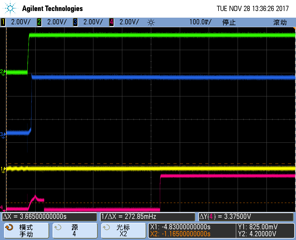
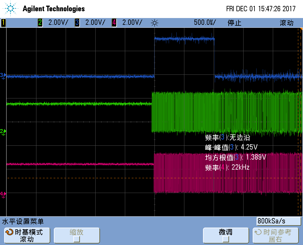
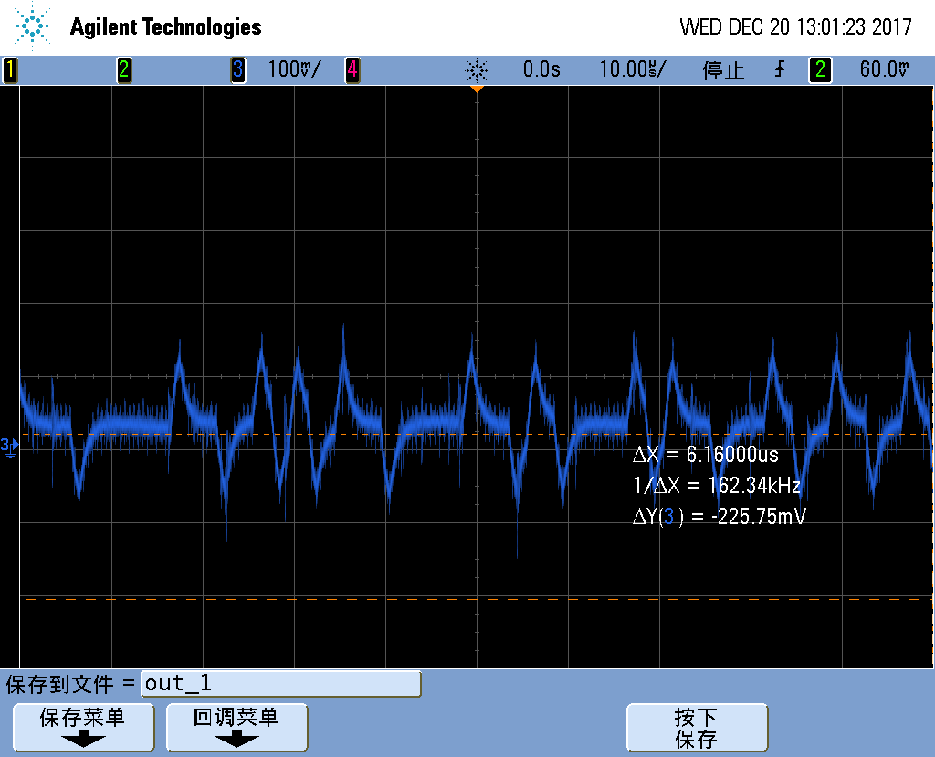
Please check the figure 1. The red line is OUT_X+ waveform. The blue line is OUT_X- waveform.
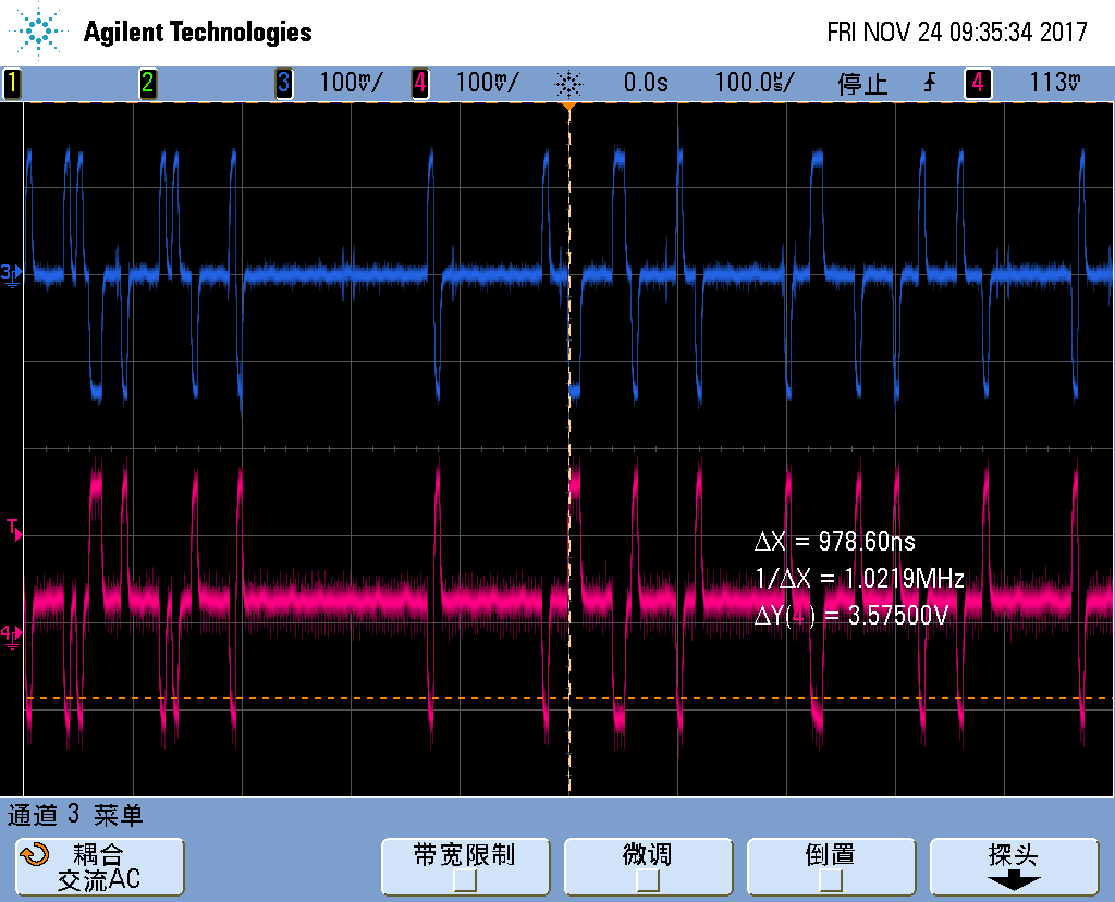
figure 1
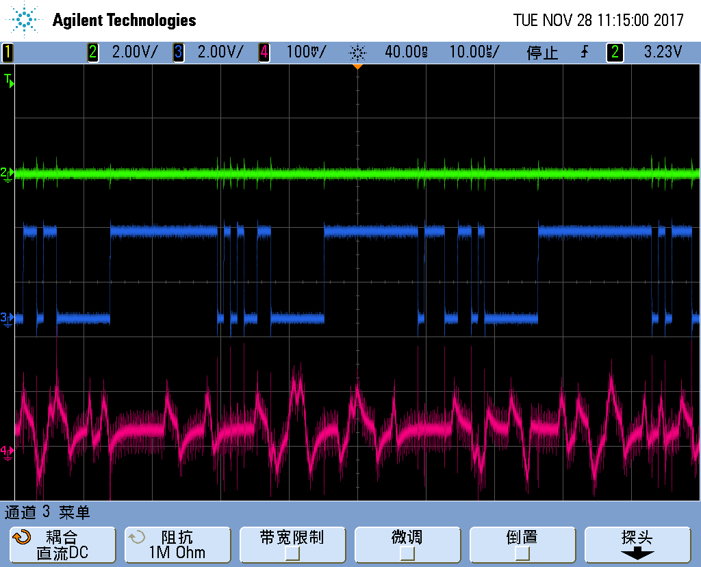
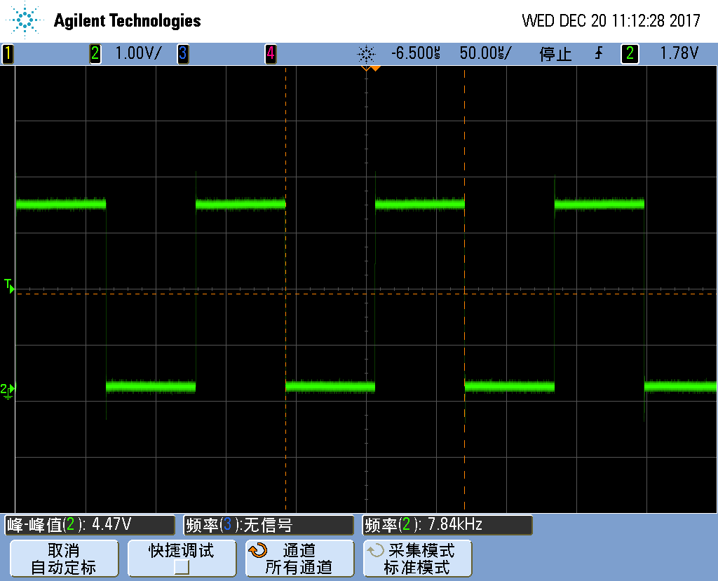
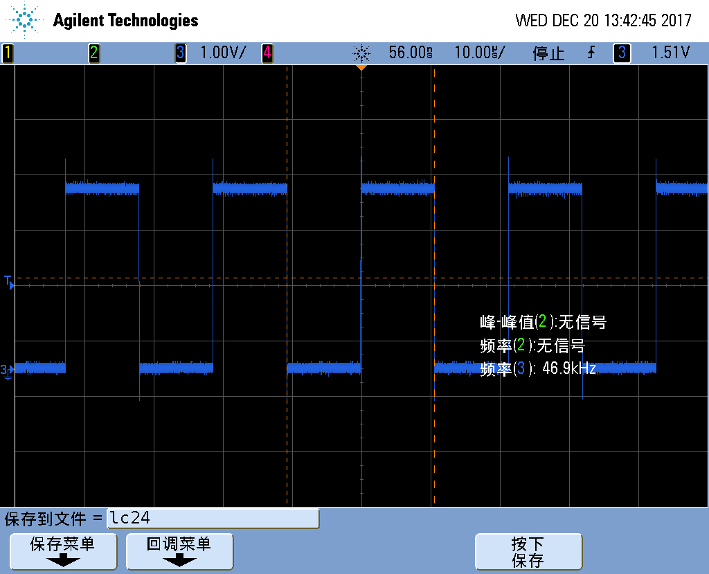
The figure 2 is the VOUT_x- waveform and the DINx waveform. There is no input signal in this case. The red wave is VOUT_x- waveform.
The blue line is DINx waveform.
figure 2
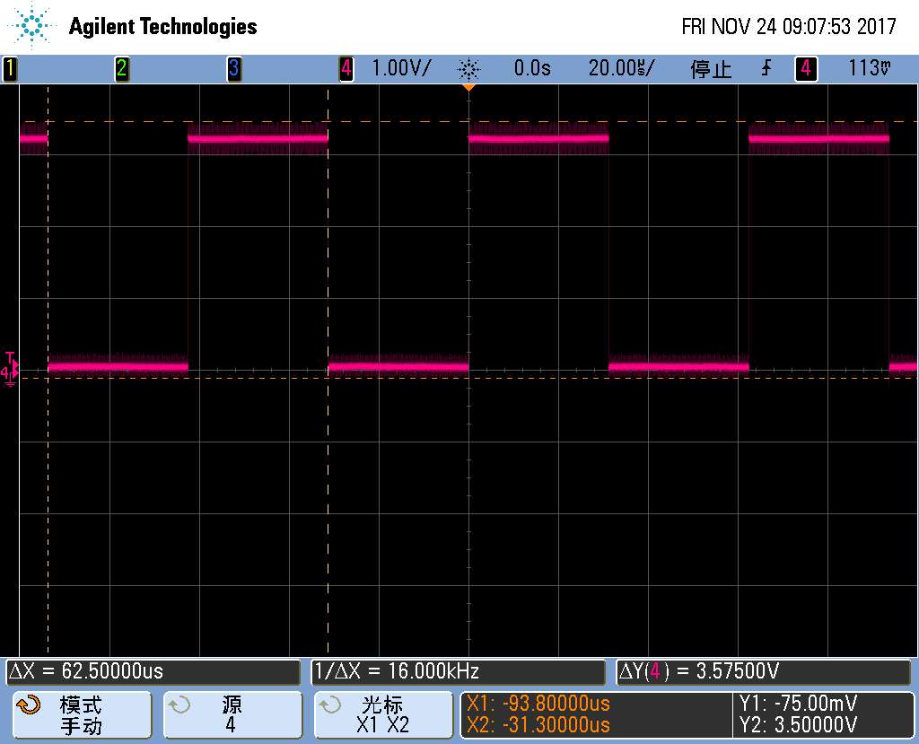
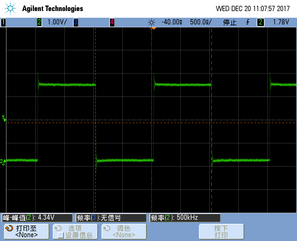
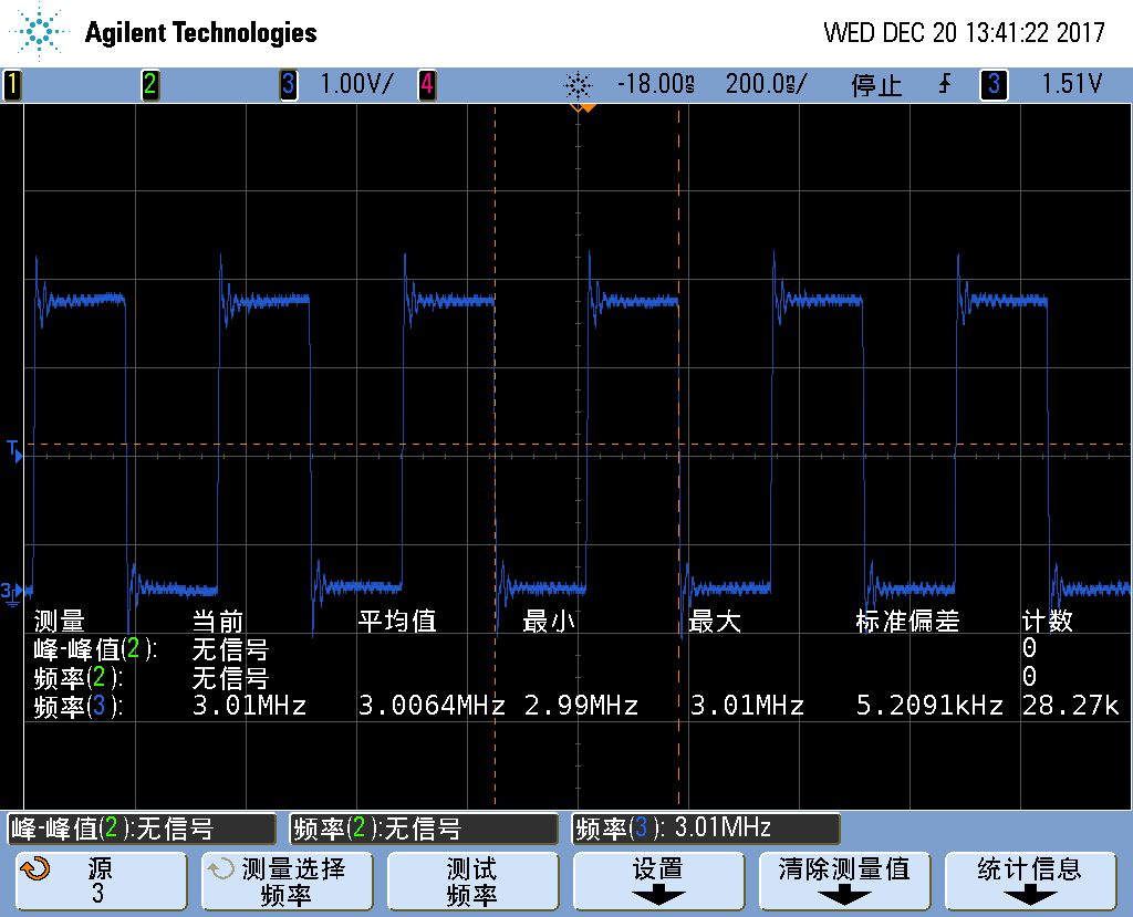
Case 2: If the customer changes the SCKI frequency from 4.096M to 8.192M ( increase by one time), the OUT_X waveform will change
from 85kHz to 169kHz. Please check the figure 3.
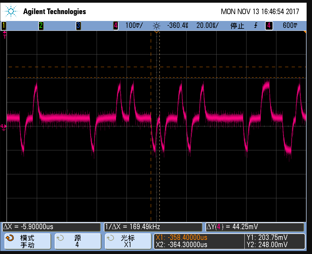
figure 3
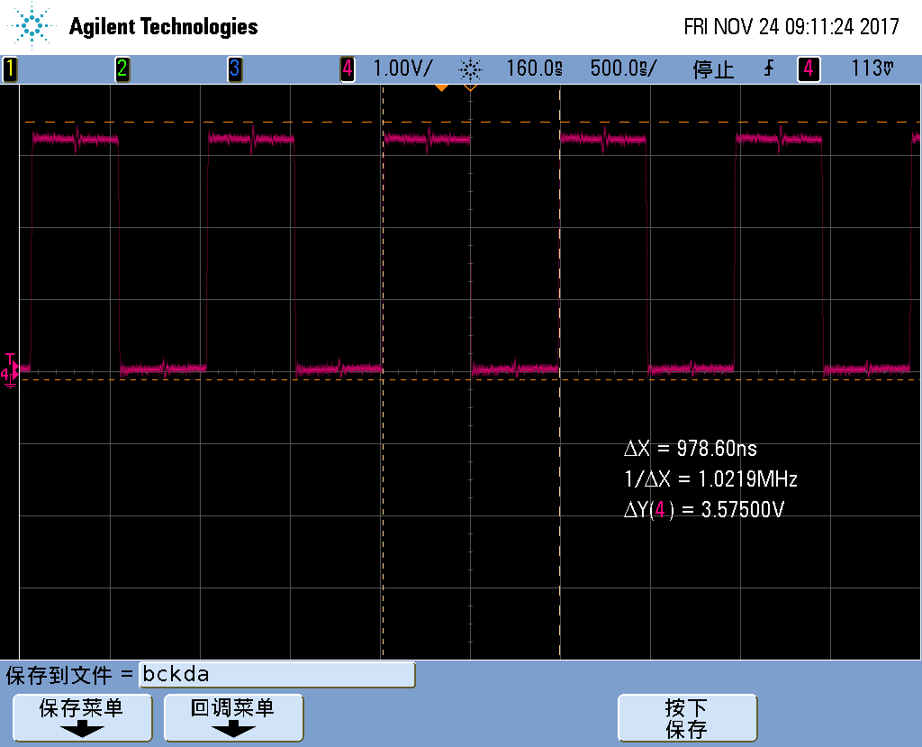
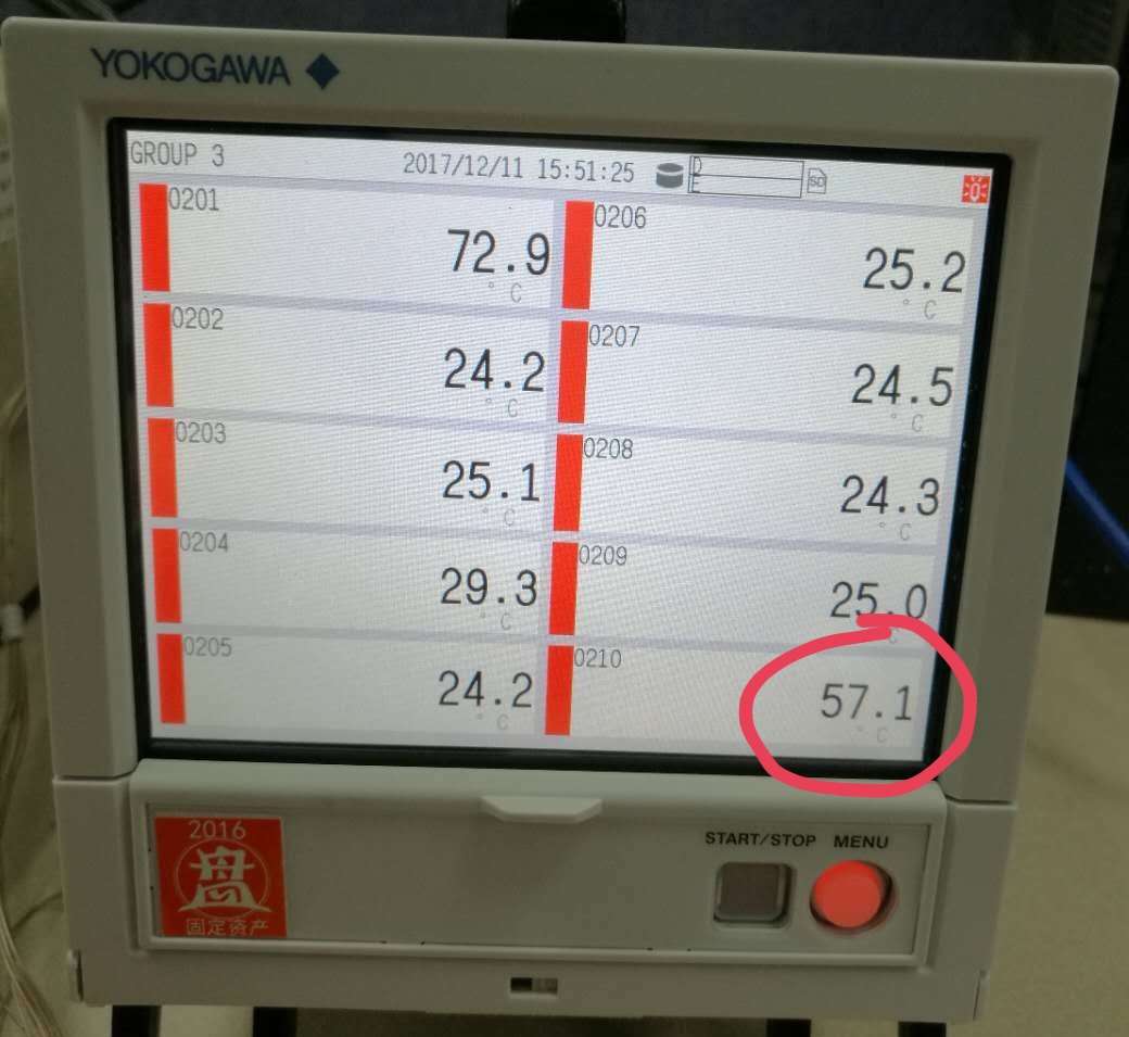
Case 3: Then the customer check his external crystal. His external crystal waveform is in the figure 4. It is fine.
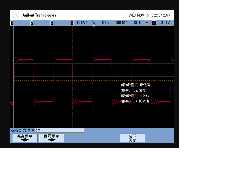
figure 4
Case 4: If the customer keep the crystal working and pull down the reset pin, the OUT_X pins will be fine.
The same issue has been occurred on two boards. Please check the customer's schematic in attach.
For the customer's issue, would you provide some suggestions?
Best Wishes,
Mickey Zhang
Asia Customer Support Center
Texas Instruments
Hi, Mickey,
The schematic in general seems fine, so maybe thew issue is related to the power sequencing.
Do you have more information about the power sequence customer is using?. Even if the power-on Reset sequence is finished, a previous RST release is recommended. In general, it is recommended to keep RST pin in LOW state until all the power supplies are stable.
What is the target sampling rate for Customer's system?. Could you please ask them to monitor DOUTx as well?. Is the issue repeated across multiple devices in the same board and viceversa?
Best Regards,
-Diego Meléndez López
Audio Applications Engineer
Dear Diego Melendez,
I'm the customer who report this issue,and let me offer some supplementary information for you:
1) Figure 1 is the power sequence of the PCM3168A, The green line is +3.3V power supply, the blue line is +5V power supply, the yellow line is OVF pin's waveform and the red line is RST pin's waveform. I monitor the OVF pin because the datasheet describe that “The OVF pin also indicates internal reset completion by transmitting a 4096 SCKI width pulse” . According to illustration 1, RST pin is keeping in LOW state for above 350ms after all the power supplies were stable. But I can't detect a 4096 SCKI width pulse from the OVF pin. I'm not sure is that a problem?
Figure 1
2) I uses PCM3168A in master mode ,so I configure the DAC channles after power-on reset,and the DAC's configurations are as follows:
1、Power-save enable;
2、Master mode 256fs;
3、DAC Audio interface format select 24-bit I2S format;
4、All DACx are in normal operation mode;
5、All DACx's Digital filter are in sharp roll-off mode;
6、All DACx are normal output(not inverted);
7、Mute disable;
8、DAC Attenuation mode:All channels with preset (independent) data + master (common) data in decibel number;
9、DAC Attenuation speed: = N×2048/fs;
10、DAC Digital de-emphasis function Disable;
11、DAC Zero flag function select:8 channel zero input detect with AND logic (default);
12、Zero flag polarity select high;
After configuration had been done,I rechecked the DOUTx and found out the clutter had transformed, and its waveform show in figure 2. The green line is DINx‘s waveform(there is no data), the blue line is DOUTx‘s waveform, the red line is VOUT_x-‘s waveform (VOUT_x+‘s waveform is just the same but phase opposited)
Figure2
3) Because the external oscillator is 4.096 MHz,so the sampling rate(LRCKAD/DA) is 16kHz, its waveform shows in figure 3, and bit clock (BCKAD/DA)is 1.024MHz, its waveform shows in figure 4
Figure 3
Figure 4
4)I have only trial-manufacture two boards,and they have same problem.
Sorry for my poor english.
Thank you for your attention and looking forward to your suggestions!
Best Regards,
Howie Li
Hardware Engineer.
Hi, Howie,
Sorry for the late response. I think the Overflow flag not sending the small pulse is an indicator that the internal Power-On reset process is not completed successfully. Is it possible to monitor the internal regulators and look for any anomaly?.
I will take a detailed look to the information you provided and will get back to you as soon as possible.
Best Regards,
-Diego Meléndez López
Audio Applications Engineer
Hi, Diego Melendez,
About the OVF pin not sending pulse problem I reported last time, now I think it is my oversight, it may be not a problem. Because There is a description in the section 9.3.6(Reset Operation) says “If the synchronization is not held, the internal reset is not released and both operating modes are maintained at reset and power-down states;” I use the PCM3168A in master mode, therefore there is no clock signals will be emitted to the LRCKAD/DA、BCKAD/DA pins, then the synchronization will not exist. So I think the OVF pin not sending pulse in the power-on moment is reasonable.
Today, I monitored the OVF pin again. This time I choose the very moment just after the PCM3168A run throngh the initialize function and became master mode. The waveform shows in Figure 1,blue line is OVF pin waveform, green line is BCKDA and red line is BCKAD. It shows that these three pins can be monitored proper signal after the initialization. So I think internal reset has completed. By the way, the clutter waveform I show you last time is also monitored after the initialization.
Figure 1 (Pluse's width is 1ms)
Our software engineer want to show you his initialize function and we hope you can help to confirm weather it is correct if it’s not too much trouble. I paste it as follows:
**************************************************************************************************************************************************************************************************************************
void PCM3168_Init()
{
//reset mode register
PCM3168_writeReg(0x40, 0x41);
while((PCM3168_readReg(0x40)&0x80)!=0x80);
printf("reset PCM3168 mode register ok!\n");
//reset ad/da
PCM3168_writeReg(0x40, 0x81);
while((PCM3168_readReg(0x40)&0x40)!=0x40);
printf("reset PCM3168 clk ok!\n");
PCM3168_writeReg(0x41, 0x40);//Power-save enable mode,Master mode, 256 fS,24-bit I2S format
PCM3168_writeReg(0x42, 0x00);//DAC normal operation,DAC sharp roll-off
PCM3168_writeReg(0x43, 0x00);//DAC normal output
PCM3168_writeReg(0x44, 0x00);//DAC Mute disabled
PCM3168_writeReg(0x46, 0x80);//All channels with preset (independent) data + master (common) data in decibel number
PCM3168_writeReg(0x50, 0x01);//AD Single rate
PCM3168_writeReg(0x51, 0x40);//AD Master mode, 256 fS,24-bit I2S format
PCM3168_writeReg(0x53, 0x3f);//single-ended input
PCM3168_writeReg(0x57, 0x80);//All channels with preset (independent) data + master (common) data in decibel number
}
**************************************************************************************************************************************************************************************************************************
In addition, I wonder if you have the PCM3168A demoboard? If so, could you please check the VOUT± pin to see the waveform when it run in master mode. I really want to know what’s the normal output waveform looks like. Thank you very much!
Best Regards,
Howie Li
Hardware Engineer.
Hi, Diego Melendez,
There is a noteworthy point I want to tell you today. During the debugging I found the chip(PCM3168A) was hot, and I checked the temperature of the shell. Result is shown in Figure 1, the temperature was up to 57℃ while ambient temperature was about 25℃ ,I wonder is it normal? Thank you!
Figure 1
Best Regards,
Howie Li
Hardware Engineer.
Hi, Howe,
Thanks for the feedback. The device is expected to get a bit hot, so maybe the temperature increase is normal. Coming back to the issue, The register setting seems fine, I wonder if you could be able to use an external digital audio source and use the device in slave mode (no register write is required) to try to replicate the issue. Another thing to try would be to use the device with the default registers and just write the required commands to set the device in master mode.
Unfortunately, there is no EVM available for this part now, this device is mounted on a controller board I have so I may be able to check if the issue is replicated.
Best Regards,
-Diego Meléndez López
Audio Applications Engineer
Hi, Howie,
Correct, the controller board I have has the PCM3168A set as Slave device, It is complicated to change it to Master mode as I need to rework the board , but will try to make the changes to test your setup.
Best Regards,
-Diego Meléndez López
Audio Applications Engineer
Hi, Diego Melendez,
I have reworked my board for using the device in slave mode. Clock signal was provided by OMAPL138, and we have tried two different frequency(4MHz, 24MHz), but the issue still occurred while there was no data input.
1. OMAPL138 was initialized to provide a 4MHz Clock to PCM3168A’s SCKI pin, sampling frequency fs = SCKI/512 = 7.8125KHz. The waveforms of SCKI, LRCKDA, BCKDA and VOUTx± are shown as follows:
Figure 1 SCKI (SCKI = 4MHz)
Figure 2 LRCKDA (SCKI = 4MHz)
Figure 3 BCKDA (SCKI = 4MHz)
Figure 4 VOUTx± (SCKI = 4MHz)
2. OMAPL138 was initialized to provide a 24MHz Clock to PCM3168A’s SCKI pin, sampling frequency fs = SCKI/512 = 46.875KHz. The waveforms of SCKI, LRCKDA, BCKDA and VOUTx± are shown as follows:
Figure 5 SCKI (SCKI = 24MHz)
Figure 6 LRCKDA (SCKI = 24MHz)
Figure 7 BCKDA (SCKI = 24MHz)
Figure 8 VOUTx± (SCKI = 24MHz)
Although the amplitude of the clutter become smaller when SCKI = 24MHz, I think it is still abnormal.
This time we only wrote the “Reset Control” register to reset the mode control register and system, and no more register was written. The initialized function is shown as follow:
void PCM3168_Init()
{
//reset mode register
PCM3168_writeReg(0x40, 0x40);
while((PCM3168_readReg(0x40)&0x80)!=0x80);
printf("reset PCM3168 mode register ok!\n");
//reset ad/da
PCM3168_writeReg(0x40, 0x80);
while((PCM3168_readReg(0x40)&0x40)!=0x40);
printf("reset PCM3168 clk ok!\n");
}
Another thing I’m going to try is using another chip from different supplier, but it may takes some time because of the procurement process of my company.
Would you please to check the VOUTx of PCM3168A on your controller board while it is running in slave mode with no data input?
Best Regards,
Howie Li
Hardware Engineer.