This thread has been locked.

If you have a related question, please click the "Ask a related question" button in the top right corner. The newly created question will be automatically linked to this question.

OPA134: Useful opamp for audio tone from microcontroller

Part Number: OPA134

Dear,

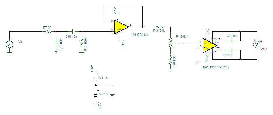
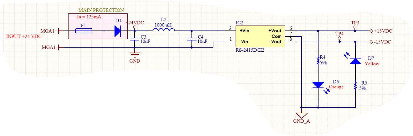
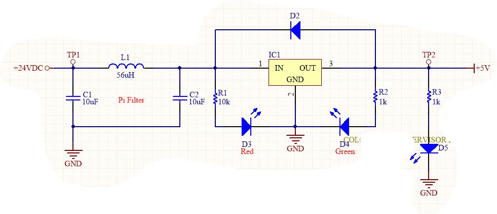
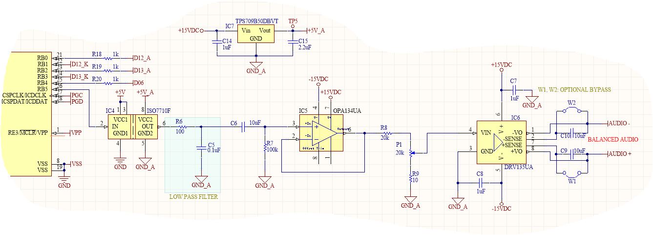
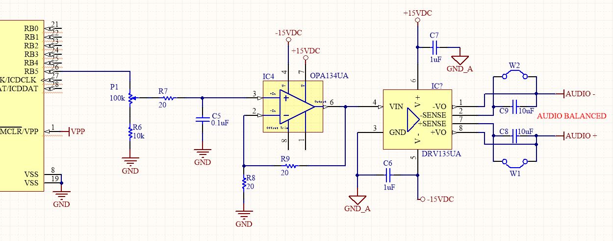
Now, I´m designing alarm tone generator with microcontroller. Microcontroller generate square signal output at 1450Hz. This output have a voltge divider and low pass filter for volume control and attenuation at frequencies outside the audio band.  I don't be sure to use a rigth opamp type. In diagram is OPA134 but could be OPA1604 for impedance coupling. Then audio is converted in balanced audio by DRV135 and so transmitt a large distance to amplifier equipment. Opamp use a dual supply voltage +/-15V from DC-DC converter isolated and microcontroller use a regulator voltage +5V, all type of voltages have a unique source from 24VDC but differences references.

My questions ,Could I have problem in amplification of audio signal from microcontroller with reference different of opamp since opamp use reference from isolated converter? and Voltage divider P1 is rigth for volume control where this signal converted to balanced will be amplified by amplifier equipment with input mic?

Thank in you in advace for your asisstance.

  • Hi Samuel,
    The diagram doesn't appear to have gone through from my end. Would you mind re-uploading it?

    Without seeing your schematic, I can only reply to the first portion of your question: As long as the microcontroller and op amp share a common ground connection, there shouldn't be any issue with running them from different supplies. If the two don't share a ground, you'd need to use a DC blocking capacitor to prevent different ground potentials from exceeding the op amp's common mode range.
  • Thanks, Samuel,

    I would relocate the volume control after the OPA134, I think. Right now, your low-pass cutoff will vary from ~100Hz with the volume control set to minimum all the way up to ~80kHz with the volume set to it's highest setting. I'd suggest the following circuit:

    This keeps the same 80kHz cutoff frequency as before, but makes a few changes. C10 was added to block the DC component of the microcontroller's square wave output (2.5V for a 0-5V square wave). This is important because DC potential across a potentiometer can cause pops and clicks as the volume is changed.

    With C10 blocking DC from the input of the OPA134, R11 was added to provide a path to ground for U1's input bias current.  

    I relocated the volume control after the OPA134 to provide some isolation between it and the input, though it could be installed where R11 is, instead. Beyond that, the DRV135 configuration is exactly as you have in your schematic. 

    A typical line-level signal in pro audio would be +4dBu, which works out to ~3.47Vpp. This would correspond to a volume setting of around 10% on your potentiometer. I assumed that your microcontroller would output a 5Vpp waveform, and assumed that a ~10dBu output signal should cover most use cases. In order to achieve a reasonable gain range, I had to add an additional resistor, R10, which knocks the maximum gain of this circuit down to ~0dB. Since R10 needed to be equal to P1, I dropped both down to 20k to help reduce noise from large resistors. I reduced the value of R6 to 100 ohms in order to set a lower limit on the volume, though R6 could be omitted entirely if full muting was desired. As drawn (and assuming that the microcontroller output is 0-5V), this gives a volume range of ~-30dBu to +10dBu. If the microcontroller outputs 0-3.3V, R10 could be decreased to achieve the same output range.

    If you want to test this out in simulation, I'm including my TINA-TI file here

  • Hi Samuel,

    to make the low pass filtering (R7 + C5) more immune against the volume settings (P1), I would increase R7 in your circuit to about 10k and decrease P1 and R6 by a factor of 10. Eventually C5 should be decreased, if R7 is increased.

    Then, the gain setting resistors R8 and R9 are too small. I would choose R8=R9=10k, or so.

    The two signal grounds "GND" and "GND_A" should be connected together to make the DRV135 work properly. Is this a problem? Do you use the +/-15V switcher only to generate higher supply voltages, or also to provide a galvanical isolation?

    Do you really need the DRV135? The OPA134 is strong enough to drive long cables. Or do you need a balanced output signal?

    Kai

  • Hi Alexander,

    Thank you for your partial response. Due to microcontroller and opamp don't share the same common ground, I will use an isolate digital or optocoupler, Could you recommend any device?.

    You said that I'd need to use a DC bloking capacitor, Could explain how can protect op amp common mode range agains different ground potentials?.

    Thanks

  • Hi Samuel,
    Looking at your power supply schematic, I'm not sure I see the reason for split analog and digital grounds in this case. If you could tie the two grounds together, even using a resistor or net tie to allow you to route your analog and digital grounds separately, then I don't think there's any real issue.

    If you can't tie the two grounds together directly, I'd recommend using two DC blocking capacitors. One as shown in my reply above - in line with the input to the OPA134, and one to couple the two ground nets together. In this case, your OPA134 and DRV135 should use the analog ground net, instead of the digital ground net as shown in your original schematic.

    Two blocking capacitors are required in order to provide a return path for the signal. The first DC block will allow the AC component of the microcontroller's output to couple into the input of the amplifier. The second block is required to give a path for the return current to flow back to the microcontroller's ground pin.

    Kai also raises a good point, and one that I forgot to include in my earlier response. If you do configure the OPA134 for gain, 20Ω resistors may put too much load on its output. 1kΩ or 10kΩ is a more typical value, with lower values creating less noise.
  • Hi Samuel,

    I agree with Alexander: Why using isolated analog and digital grounds? This can create a bunch of problems instead of solving them.

    Also, take care with the pi-filters: You will get huge ringing if the ESR is too little. R >= SQRT(2L/C) is necessary to prevent overshoot and ringing.

    Kai
  • Hi Alexander,
    Good Idea, I agree to change position for P1. The control volume is essential because I use an audio multiplexer where in conjuntion with stations (like one direccion intercom), each one be setting up a minimum line-level of amplifier equipment.
    I have to check maximun line-level signal for input amplifier equipment when this is selected for mic input channel.
  • Hi Samuel,
    One other thing to consider is that microphone-level inputs are typically much lower level than line-level. This shouldn't be an issue if the equipment you're driving has a gain control, but I wouldn't go much over the standard +4dBu pro audio line level.
  • Hello Kai,
    I try to separate the control and the audio signal. The dual supply voltage is only for opam'p and driver. I need a balanced output signal because I route a large distance from the generation audio source to the amplifier equipment.
  • Hi Samuel

    We haven't heard back from you so we assume this resolved your issue. If not, post a reply below, or create a new thread if this one has timed-out.

    Thanks

    Dennis
  • I improved the design adding Single-Channel Digital Isolator ISO7710F for avoid problem for use no common ground, increased value of R6 to 100 ohm in low pass filter in order to obtain cutoff frequency of 16 kHz about and decreased R9 to 10ohm.

    I attach new circuit where I renumbered components. I hope this work fine, please verify it.

  • Hi Dennis,
    I just posted with the last modification in my design so you can help me in the verification
  • Hi Samuel,
    This looks like it should work. The only change I would suggest would be to increase R6 to 1kΩ and decrease C5 to 10nF. Right now, I'd expect to see peak currents out of IC4 of around 50mA, which exceeds the max output current of the ISO7710. Increasing R6 will help reduce this current.

    Aside from that, I don't see any issues. Let me know if you have any further questions. If not, I'll go ahead and mark this thread as closed, but you can reopen it by replying.
  • Hi Alexander,
    How do you calculate that value 50mA? or do you use TINA?
  • Hi Samuel,
    This was a rough calculation. Assuming that C5 starts off fully discharged, when the microcontroller first pulls that output to +5V, the full 5V will be dropped across R6, giving 5V/100Ω = 50mA. This may not be realistic as a steady-state current, since C5 should end up at around 2.5V on average, but peak currents during startup could go higher. It may be safer to increase R6 and decrease C5 to maintain the same cutoff frequency while decreasing that peak current.
  • Hi Alexander,
    Thank you for your clarification and help.