This thread has been locked.

If you have a related question, please click the "Ask a related question" button in the top right corner. The newly created question will be automatically linked to this question.

PCM5242: PCM5242 multiple Balanced Output Impedance problem

Part Number: PCM5242
Other Parts Discussed in Thread: INA2137

Hello,

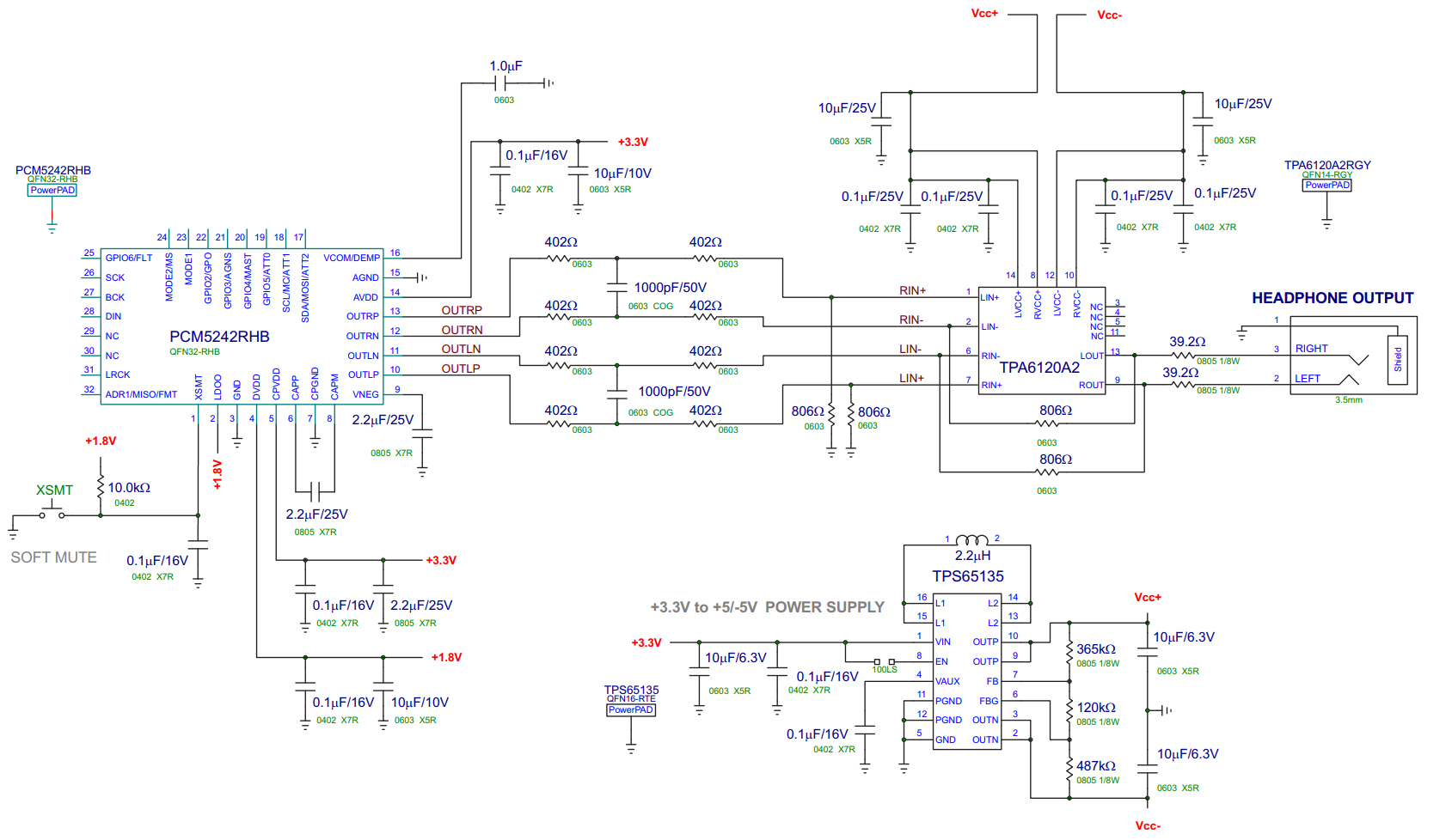
We have an actual design using PCM5242 + TPA6120 + INA2137. Until here everythings works as expected, the problem is when we try to use the balanced output for an external amplifier.

I think there is some impedance problem when connecting balanced lines to the external amp/capture soundcard. This is how we've implemented parts on our design.
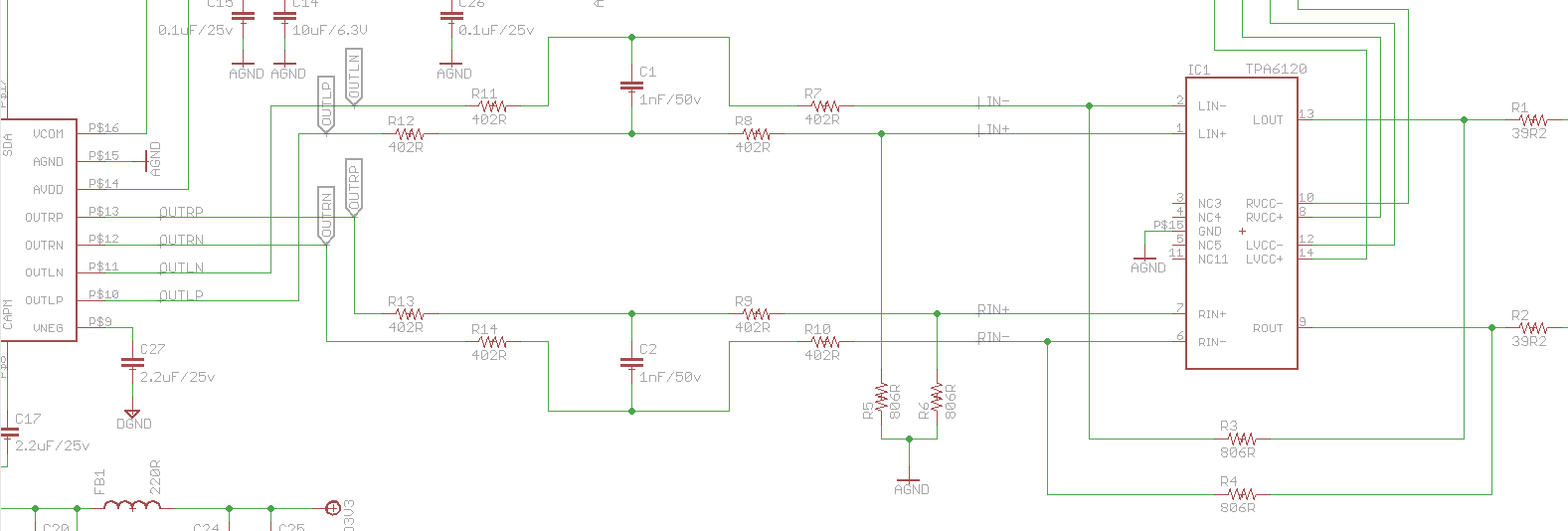
Suggested for XLR:

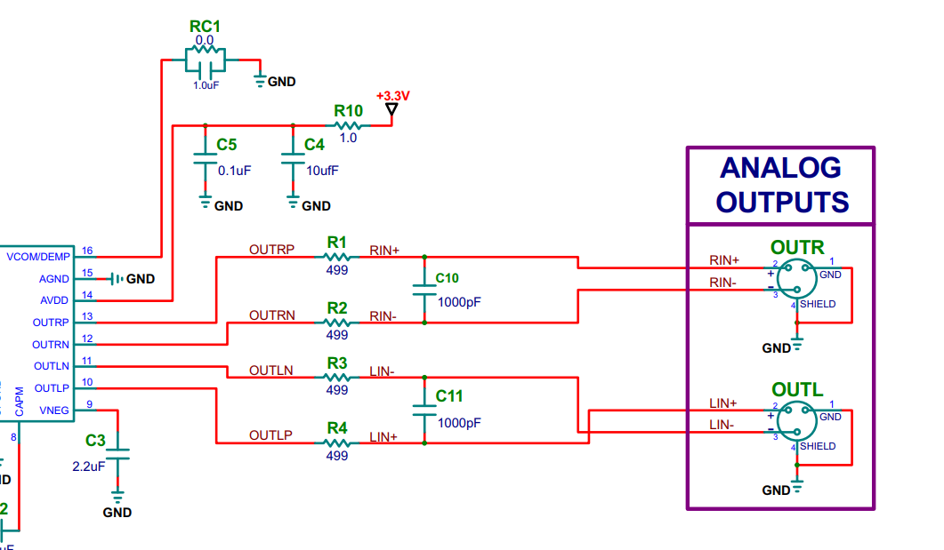
Should we add the 499 resistors plus 1000pf capacitor as suggested on EVM board for XLR on green points or should we tie the output from the points marked on red? If the last one, will that affect the impedance for the TPA and INA devices? Is the INA2137 well connected?  (that way works fine)

Thank you!

Oriol.

  • Sorry here schematic with marks:

  • Hi Oriol,

    I believe you are violating the minimum output impedance of the PCM5242.  If you consider the output OUTLP, you have a 402+402+806ohm path to ground. 

    The minimum output impedance is 5kOhm for this device.  I recommend you either buffer the individual outputs of the PCM or increase the values of the gain resistors for the TPA to values that do not violate this specification.

    Thanks!

    Paul

  • Hello Paul,

    Thank you for your fast response.

    I have already seen that, but you also suggest it to use with the TPA6120, that's actually on the PCM5242 datasheet:

    Anyway that part is working perfect, so I just want to have an idea about the XLR output. On your suggestions there are many implementations that I don't understand because are quite different.

    Thank you!
    Oriol.

  • Hi Oriol,

    That's a good point about the datasheet! :)

    What is the symptom when you connect the INA2137? Does the output clip?

    Thanks!
    Paul
  • Hi Paul,

    Yes, that's why I'm going crazy about impedances! :)

    So beforethe INA2137 was connected to "red" points, and there was cliping, now is connected directly to output of PCM5242 or to green points, and no more clipping. I don't understand because here the Vrms is higher from the output!

    Also another weird thing is that actually the INA output is higher than the TPA one, with a load impedance of 600Ohm, output is lower on TPA, what makes no sense actually to the design. Tried to change value of the resistors but then TPA clips. Also to consider that the INA2137 has G=2, that's also why it's output is higher than the TPA6120. But I would like to have a better performance on it.

    Actually at 95% Vrms works well, clipping is not even there. Also to consider that amplifier volume is at 10%, so I can go down on output, but then for headphones the output will be really low. I have not tried on 32ohm headphones because only using studio ones, upper than 300 Ohms.

    Datasheet says that TPA is configured on that schematic to 1V/V, some way to change it to 2V/V avoiding clipping? Datasheet of it suggest using 1K resistors for Rf and Ri, but actually closer to 806 ones.

    An then here also again my first question, where to get the XLR output! Directly from PCM5242 on green points, from there but using resistors suggested plus caps? Or directly from the "red" points? :)

    Thank you!

    Oriol.

  • Hi Oriol,

    I think the reason you have issues when using the red points is that the various resistors on each amplifier are effecting each other.  In addition the R11-13 values will change the gain of the INA2137 even without the TPA on the system.  Try playing with the TINA model I have created.  One though could be to use the INA2137 as a buffer for the PCM, then have the TPA and XLR connectors both connected to the output of the INA.  Basically using the amps in series rather than in parallel.

    TINA Model.TSC