This thread has been locked.

If you have a related question, please click the "Ask a related question" button in the top right corner. The newly created question will be automatically linked to this question.

TAS5755M: No output from Amp

Part Number: TAS5755M

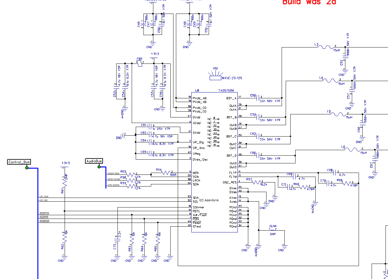
This is a new design prototype for a Bluetooth Speaker project.  I'm driving this Amp from a TLV320 that is configured for 16 bit I2S output and the project is a respin to introduce the TAS5755M as a replacement for an Analog Devices Amp and it worked before so I'm pretty confident that the TLV320 is set up correctly.  I can see 16 bit stereo I2S data going into the TAS5755M.  I followed all the setup procedure for the Amp and can read the registers that I wrote to to confirm that they are set to what I requested.  I own the TAS5755MEVM setup too.  After advice on this forum and a test using the TAS5755MEVM boards, I fed the I2S Sclk signal into MClk and Sclk; LRClk and SDin are fed by their own signals. The register setup for the TAS5755M is as follows...

void setupTAS5755M(void)
{
    // See notes on this at p61 of TAS5755M.pdf DS
    VbattSwEn_Write(0);                                 // turn off +12V switched
    UART_UartPutString("Setting up TAS5755.. ");
    nPDN_Write(1);                                      // disable PwrDowN
    nReset_Write(0);                                    // enable Reset
    CyDelayUs(120);                                     // info says wait at least 100 uS
    nReset_Write(1);                                    // disable Reset
    CyDelay(15);                                        // info says wait at least 13.5 mS
    VbattSwEn_Write(1);                                 // turn on +12V switched
    
    I2C_Write1(TAS5755_ADDR, trimOscillator, 0x00);     // perform Oscillator Trim
    CyDelay(52);                                        // info says wait at least 50 mS
    I2C_Write1(TAS5755_ADDR, SerDataIF, 0x03);          // I2S 16 bit
    I2C_Write1(TAS5755_ADDR, Sys_Ctrl2, 0x42);          // Exit Shutdown procedure (p62 in DS)
    CyDelay(240);                                       // info says could take up to 240 mS
    I2C_Write1(TAS5755_ADDR, Master_Vol, 0x80);         // Set Mast Vol to sensible level
    I2C_Write2(TAS5755_ADDR, Chan_1_Vol, 0x08, 0x08);   // Set L+R Vol to +20dB (2 bytes so it gets Left + Right)
    I2C_Write1(TAS5755_ADDR, Soft_Mute, 0x00);          // unmute
}

After I power up and give an input signal, I have I2C volume change commands that execute without (I2C) errors as follows...

I2C_Write1(TAS5755_ADDR, Master_Vol, MastVolVal); // write to master volume value register

Where MastVolVal is as low as 0x10 and Master_Vol is set to 0x07

I thought it may be because the TAS5755M defaults to 24 Bit I2S so I added the line that sets SerDataIF (Addr 0x04) to 0x03.

An I2C read back of the registers starting at 0x00 is...

0x6C 0x00 0x00 0xA0 0x03 0x42 0x00 0x7B 0x08 0x08

When the Amp is in a state that I think it should be producing sound.

Any ideas?

  • Ted,

    Decoding the register map, I deduce the following:

    0x00 = 0x6C: Fs = 44.1k or 48k, MCLK = 256*Fs.
    0x01 = 0x00: ID code
    0x02 = 0x00: No Errors
    0x03 = 0xA0: PWM High Pass enabled, Hard unmute recovery from clock error
    0x04 = 0x03: 16 bit I2S
    0x05 = 0x42: Mid-Z ramp disabled, ALL CHANNEL SHUT DOWN (HARD MUTE), sub channel AD mode, 2xBTL mode, ADR/FAULT as fault output.
    0x06 = 0x00: Soft Unmute all channels
    0x07 = 0x7B: Master volume
    0x08 = 0x08: CH1 volume
    0x09 = 0x08: CH2 volume

    I would say it's the 0x42 setting of register 0x05, all channels are in hard mute shut down. Double check that's correct.

    See datasheet page 63, "10.2.1.2.4.3 Shutdown Sequence"


    Regards,

    -Adam


    If your question was answered, please click the "This resolved my issue" button!

  • Adam,

    Thanks for identifying that issue but I'm still hearing nothing :(
    My dump of the registers (starting at 0x00) is now ...
    0x6C 0x00 0x00 0xA0 0x03 0x00 0x00 0x80 0x08 0x08 and I've tried 25 Bit I2S (Reg 0x04 to 0x05) but still no sound.

    I've checked that all the components are there traced the speaker connections from the Amp to the speakers - that all seems fine. I can see the digital signal coming in as expected so it most likely is still a setting.

    My speakers are connected in 2.0 mode, L + R speakers where one is driven by A+B and the other by C+D; I'm not using any of the internal equalization, I just want raw I2S to come out of the speakers. Is there some MUX setting that I should be concerned about?

    Ted
  • Ted,

    I'm not sure what the issue is in that case. Without being able to see your setup directly, I can try and set up the same here and check if I have the same problem.

    The above testing is using the TAS5575MEVM correct?

    What's the complete part number of the TLV320? That part number is generic for a whole family of codecs.

    Regards,

    -Adam


    If your question was answered, please click the "This resolved my issue" button!
  • Adam,

    This is my own hardware but it's based on the TAS5575MEVM board - part of my schematic is attached.  I switch the +12V to the PVdd supplies via a FEt as part of the power up and, the first time, this obeys the rule of...

    "Ramp up PVDD to at least 8 V while ensuring that it remains below 6 V for at least 100 μs after AVDD/DVDD reaches 3 V. Then wait at least another 10 μs."

    which is on P62 of the datasheet  (para 10.2.1.2.4.1 Initialization Sequence) but, if I recycle the power, the 4 x 100 uF caps on PVdd hold it at over 6 volts for several minutes so the +12V supply is maintained by the caps even though the +3.3V may disappear.  Is this a big issue?  Might it have damaged the Amps? Do I need to add circuitry to discharge the caps as part of the power initialization?

    Ted

  • I added a 0.1 W 2k resistor across the PVdd caps so they will discharge to under 4.5 V in 0.8 seconds but only draw 6 mA (0.072W) so now I am obeying the startup rules all the time. I still get no sound but I tested the digital signals were going to the TAS5755M and I also scoped the inputs to the main output inductors L3,4,5,6 and they all are being fed with a square wave drive of about 350 kHz at around 12V (I had not tested this before). Does this mean it's working but has no signal routed to the Amp I wonder?
  • The complete part number of the TLV320 is TLV320ADC and it's configured by the following routine...

    void setupTLV320(void)
    {   
        UART_UartPutString("Setting up TLV320.. ");
        // the values and the order they are written in is taken from page 79-81 of DS (para 11.2.2.2)
        I2C_Write1(TLV320_ADDR, 0x00, 0x00); // set TLV320 to page 0
        I2C_Write1(TLV320_ADDR, 0x01, 0x01); // trigger soft reset the TLV320 will come out of reset on its own
        CyDelay(100);                        // but it needs time so wait 0.1 seconds for device (may be unecessary)
        // table 1 on page 23 of DS gives parameters
        // MCLK = 12 MHz, P=1, R=1, J=7, D=5264, Achieved Fs = 44.1 kHz
        I2C_Write1(TLV320_ADDR, 4, 0x03);        // p47 - Clock comes in on MCLK, CODEC_CLKIN = PLL_CLK       
        I2C_Write1(TLV320_ADDR, 5, 0x11);        //       P = 1, R = 1
        I2C_Write1(TLV320_ADDR, 6, 0x07);        //       J = 7
        I2C_Write2(TLV320_ADDR, 7, 0x14, 0x90);  //       D = 5264 = 0x1490 (Note this sends 2 bytes out in 1 write)
        I2C_Write1(TLV320_ADDR, 5, 0x91);        //       Pwr on to PLL and P = 1, R = 1
        I2C_Write2(TLV320_ADDR, 18, 0x88, 0x82); // p48 - NADC Pwr On and Val = 8, MADC Pwr On and Val = 2 (Note this sends 2 bytes out in 1 write)
        I2C_Write1(TLV320_ADDR, 20, 0x80);       //       AOSR = 128    
        I2C_Write1(TLV320_ADDR, 27, 0x0D);       // p49 - I2S, 16 bits, BCLKop WCLKop DoutEn
        I2C_Write1(TLV320_ADDR, 30, 0x88);       // p50 - BCLK N Div on and BCLK = ADC_CLK/8 = 11.2896 MHz/8 = 1.4112 MHz 
        I2C_Write1(TLV320_ADDR, 61, 0x01);       // use PRB 01 (processing block)
        // ### PAGE 1 VALUES ### (p64 onwards)
        I2C_Write1(TLV320_ADDR, 0, 0x01);        // Set register Page to 1
        I2C_Write1(TLV320_ADDR, 51, 0x00);       // p65 - Set MICBIAS to not used (prolly not needed as 0x00 is default value)
        // Program PGA level
        I2C_Write2(TLV320_ADDR, 59, 0x02, 0x02);  // p68 - Set Left, Right Analog  00 = 0dB 0x1E = +15dB (2 locations set)
        // Program routing of inputs/common mode to ADC input
        I2C_Write1(TLV320_ADDR, 52, 0xFC);        // p66 - Left ADC Input selection for Left PGA = IN1L(P) as Single-Ended
        I2C_Write1(TLV320_ADDR, 55, 0xFC);        // p67 - Right ADC Input selection for Right PGA = IN1R(M) as Single-Ended
        // Unmute analog PGAs and set analog gain
        // ### PAGE 0 VALUES ### 
        I2C_Write1(TLV320_ADDR, 0, 0x00);        // set TLV320 back to page 0
        I2C_Write1(TLV320_ADDR, 81, 0xC2);       // Power up ADC channel
    //    I2C_Write1(TLV320_ADDR, 82, 0x00);        // Unmute digital volume control and set gain = 0 dB
    }

  • When I select the TLV320ADC as the input source, the I2C command I2C_Write1(TLV320_ADDR, 82, 0x00); // Unmute digital volume control is run so the fact that 't's commented out above is not the problem, as I said before, this code was working before with a different amp.

    Is there something wrong with the I2S setup? I was told that, for specific clock rates, I could feed the TAS5755M MClk and SClk pins from the TLV320ADC SerialClock output which I've done, I've confirmed that those signals are getting to the TAS5755M and they look clean
  • Ted,

    TLV320ADC is still not the complete part number, please include the numbers following "ADC".

    If you could also provide a schematic of how you have everything connected.

    Regards,

    -Adam
  • Sorry, the full part number is TLV320ADC3101IRGER, I have also attached pdfs of the relevant parts of the schematic.

    Schematic1of3.pdfSchematic3of3.pdf

  • Hi Ted,
    I reviewed the SCH but didn't find obvious issue. Could you please help to do the following check?
    1. After the AMP initialization, can you see the PWM waveform on the output pins(OUT_A~OUT_D)? If yes, it means that the initialization is successful. If not, let’s try to use a min configuration(AD mode, BTL mode) at first.
    w reg_0x1B val_0x00 //trim OSC
    w reg_0x05 val_0x00 //AD mode, BTL, exit shutdown
    w reg_0x06 val_0x00 //unmute
    w reg_0x06 val_0x00 30//set volume to 0dB
    2. If it doesn’t work with the min cfg, please remove Rly1 and Rly2 to exclude the switch effect on the output. No sure if it causes any DC voltage or noise on the output.
    3. If PWM shows but there is still no sound, please check the volume setting. Please be noted that the master volume register has two bytes. Capture the I2C read/write operation on the register 0x07 by scope to make sure the multiple-byte read/write timing requirement in the section 9.5.1.4 and section 9.5.1.6 are followed. We know that some user read/write the multiple-byte register in the inverted order, which makes the real volume setting quite low.
    4. For most of the cases, the sound should be heard if the volume setting is correct. If still not, let’s check the format of the I2S stream from the ADC/Codec. Also make sure the I2S clock polarity(pos edge) setting is correct in ADC/Codec. Please check the signal integrity of the I2S input signal. Read the Error Status register in the register 0x02 to see if there is any error.
    Best regards,
    Shawn Zheng
  • Shawn,

    Some communication has taken place between myself and Adam S on this via email; part of that communication established that the TAS5755M does not have 2 bytes for master volume register, it has one. Are you checking my register settings against the correct IC?

    Ted
  • Hi Ted,
    I will take over this case from Adam. Give me some time to go through your previous communication, and let's continue to communicate by email.
    Best regards,
    Shawn Zheng