This thread has been locked.

If you have a related question, please click the "Ask a related question" button in the top right corner. The newly created question will be automatically linked to this question.

TLV320AIC3104EVM-K: Asking for thr AIC3104 analog input and analog output setting

Part Number: TLV320AIC3104EVM-K
Other Parts Discussed in Thread: TLV320AIC3104

Hi team,

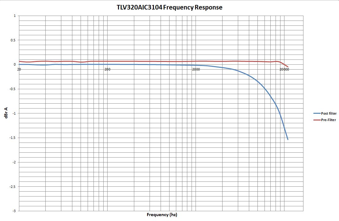
Customer request the analog input and then bypass to line out AIC3104 frequency v.s. amplitude and frequency v.s. THD chart.

Could you please help for customer request chart on the AIC3104EVM?

Here are the experiment that I would like to measure on the AIC3104EVMK.

1. use the AIC3104EVMK and use Win XP laptop. but the GUI shows no connection.

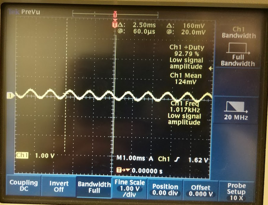
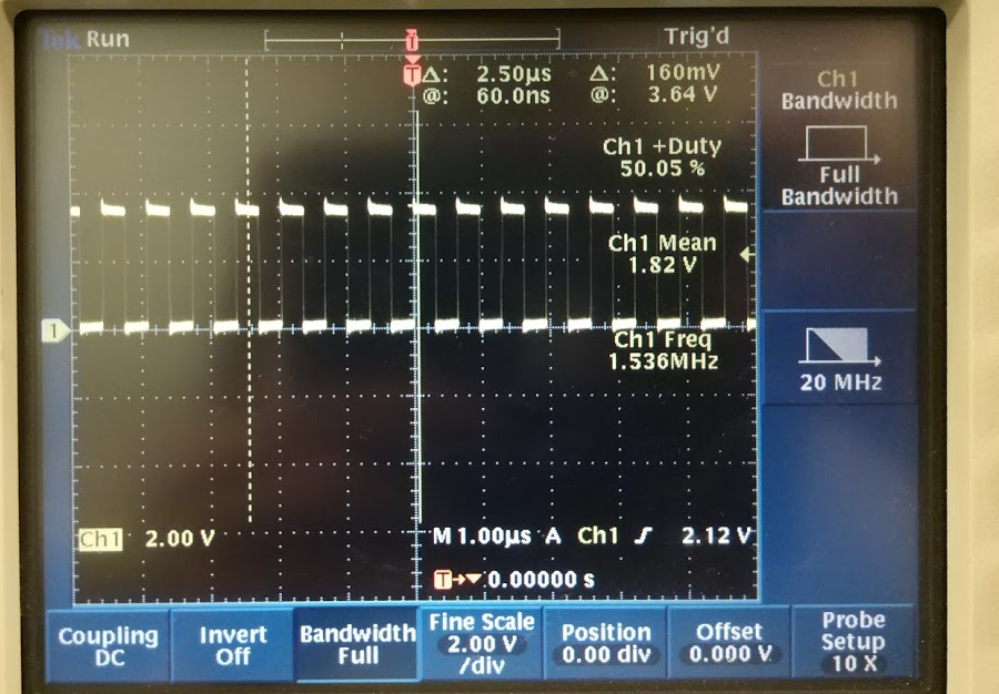
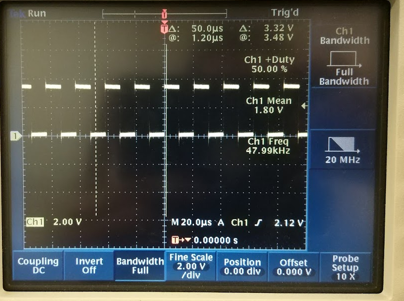
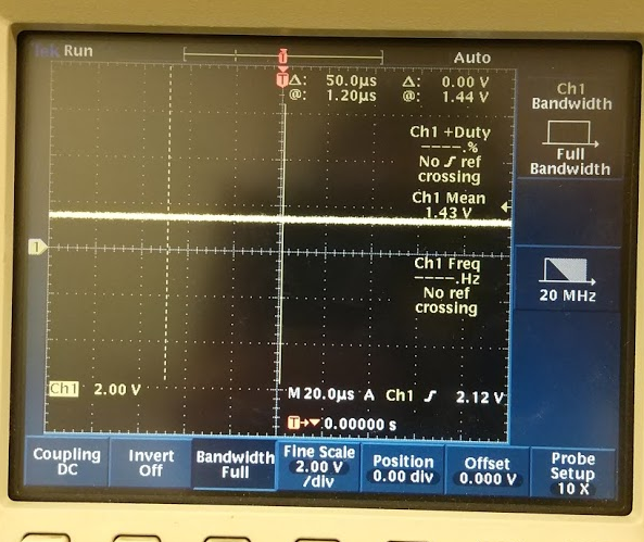
2. I use the AIC3254EVM as I2C master and use the function gen to send the 1kHz to AIC3104EVM IN1. the AIC3104 EVM I2S is from Audio precision. (12.288MHz, 1.532MHz, 48KHz) Here are the AIC3104 EVM test point waveform.

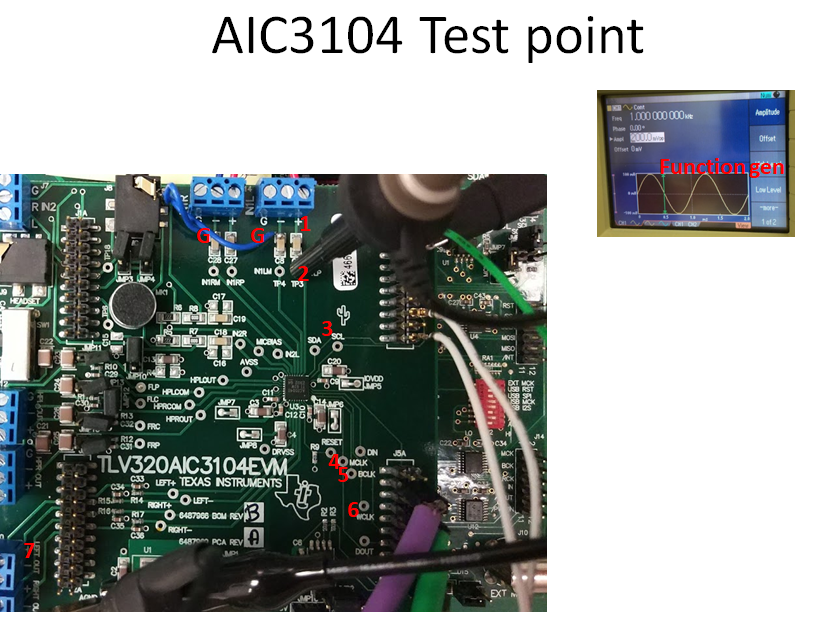
test point 1 waveform

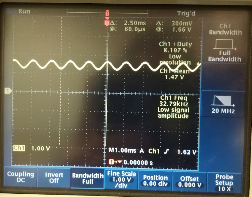
test point 2 waveform

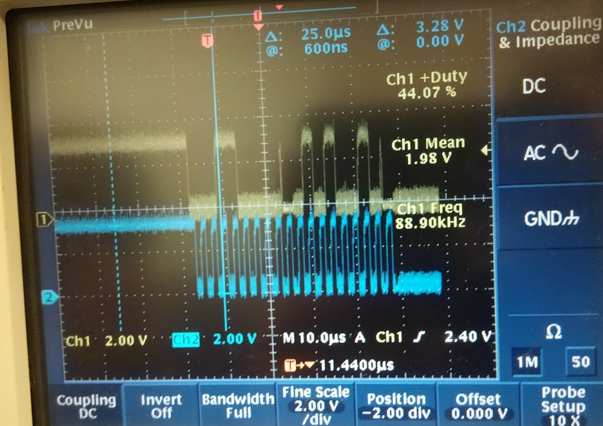
test point 3 waveform

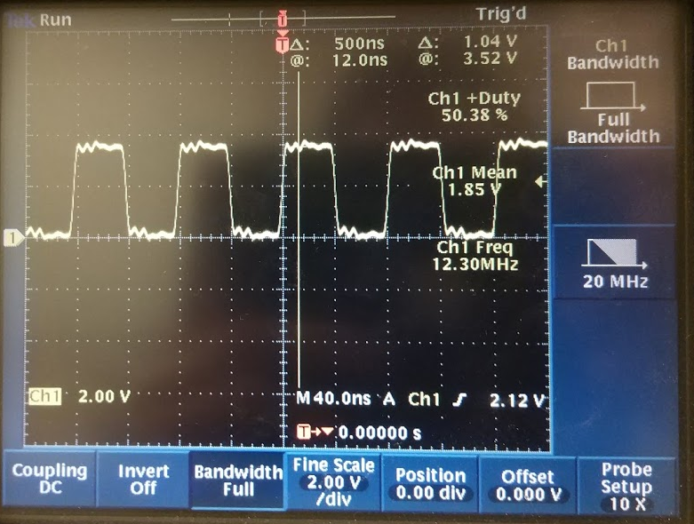
test point 4 waveform

test point 5 waveform

test point 6 waveform

test point 7 waveform

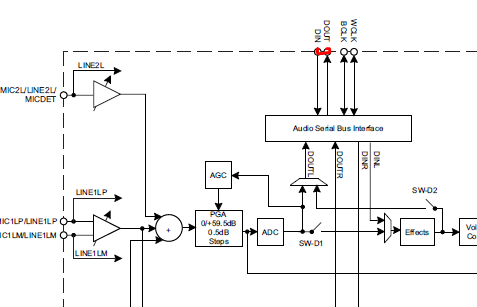
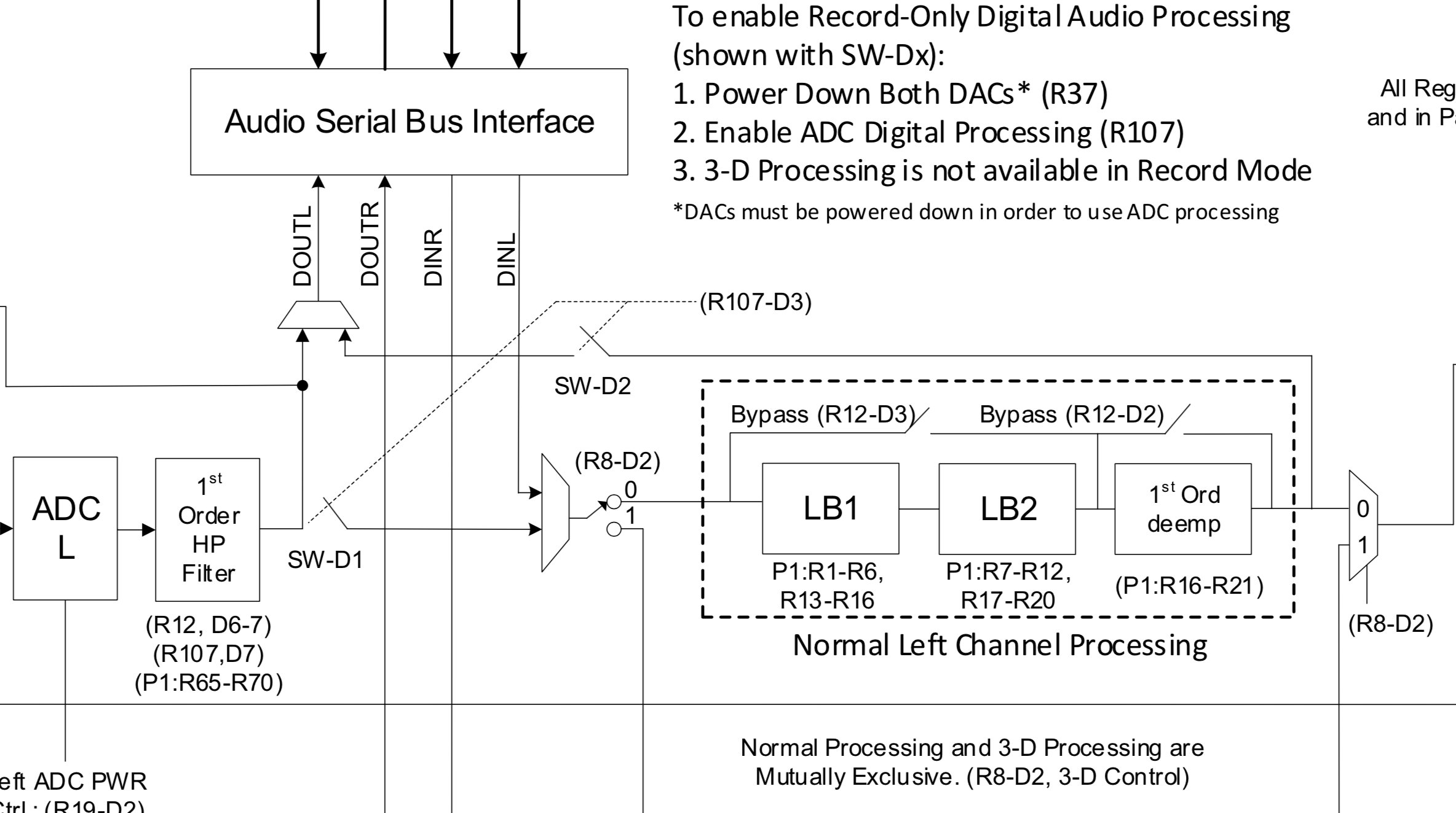
then, I followed the page 5 initial scripts. (TLV320AIC3104 Programming Made Easy www.ti.com/.../slaa403) and use AIC3254 CS tool to send the commands.

However, there is no output on the AIC3104 line outpout on J10 and J11.

Questions:
1. Do you have the AIC3104 analog input and analog output inital file .cfg?

2. could you please use AIC3104 EVMK anlogn in analog out frequency response and frequency THD?

3. Do you please review the setup and provide your comment how to make it work?

BR,
SHH

  • SHH, 

    I have a frequency response plot from a while back.  The plot shows both the filtered output and unfiltered output (there is a LPF on the line outputs to get rid of out of band noise)  the output is full-scale, but the amplitude is referenced to the amplitude of the post filter output at 1k.  

    I don't have a THD Vs frequency ready. I can run a quick test on the AP of course,  do you have a preference on the output amplitude? 

    regarding example scripts please find them below.  Example script IV is for the line outputs and example script V is for the Line inputs.

    both file assume 48khz or 44.1kHz. 

    best regards,

    -Steve Wilson

    Example_IV.txt
    DAC to Line Outputs
    
    Digital audio setup for operation with defaults of USB-MODEVM
    
    Input:
    DAC
        - left data to LDAC and right data to RDAC
        - volume control = 0dB
        - Connected to outputs via mixer mode
    
    Line Outputs (differential signals)
        - Left and Right Line outputs
        - LDAC to Left Line Outpu
        - RDAC to Right Line output
        - Mixer gain = 0dB
        - Line Output amplifier gain = 0dB
    
    Regsiter configuration:
    
    w 30 07 8A
    w 30 25 C0
    w 30 29 02
    w 30 2B 00
    w 30 52 80
    w 30 5C 80
    w 30 4B 80
    w 30 4E 80
    w 30 56 09
    w 30 5D 09
    w 30 4F 09
    
    0878.Example_V.txt
    Differential Inputs to ADC
    
    Digital audio setup for operation with defaults of USB-MODEVM
    
    Input:
    LINE1L/R differential inputs
        - Volume control = 0dB (not muted)
        - LINE1L connected to LADC
        - LINE1R connected to RADC
    
    Ouput:
    
    ADC
        - LADC ON
        - RADC ON
        - PGA gain = 0dB
        - Output amplifier gain = 0dB
    
    Register Configuration:
    
    w 30 1F F8
    w 30 15 F8
    w 30 16 84
    w 30 13 84
    w 30 0F 00
    w 30 10 00

  • Hi Steve,

    i can measure the chart for customer after several setup. however, I need to short AIC3104 DIN and Dout.

    Do you know which register that I can turn the switch SW-D1?

    BR,

    SHH

  • SHH,

    There is only one way to do audio passthrough.   DIN must be shorted to DOUT.  

    the drawing in the datasheet is perhaps not the best at showing the functionality of SW-D1 and SW-D2.   I am updating the Datasheets for the AIC310x devices, and adding a new functional block diagram with registers that will show the functionality more clearly. This is a snippet from the current Draft:

    These switches are used for "record only processing mode"  This means that the DAC processing is utilized by the ADC.  The DACs must be powered down for this to work.  The Switches SW-D1 and SW-D2 are ganged, so there is no way to enable one without the other. 

    best regards,

    -Steve Wilson