This thread has been locked.

If you have a related question, please click the "Ask a related question" button in the top right corner. The newly created question will be automatically linked to this question.

TAS5721: TAS5721 thump/click when exiting shutdown in 2.1 mode

Part Number: TAS5721

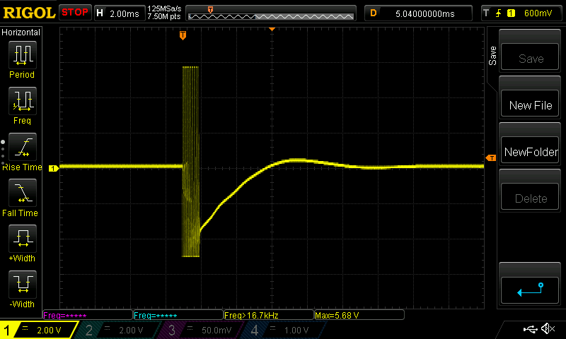
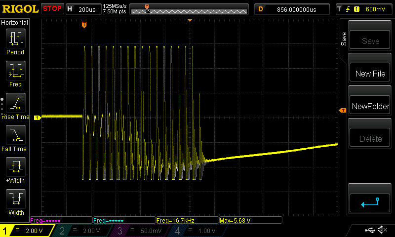
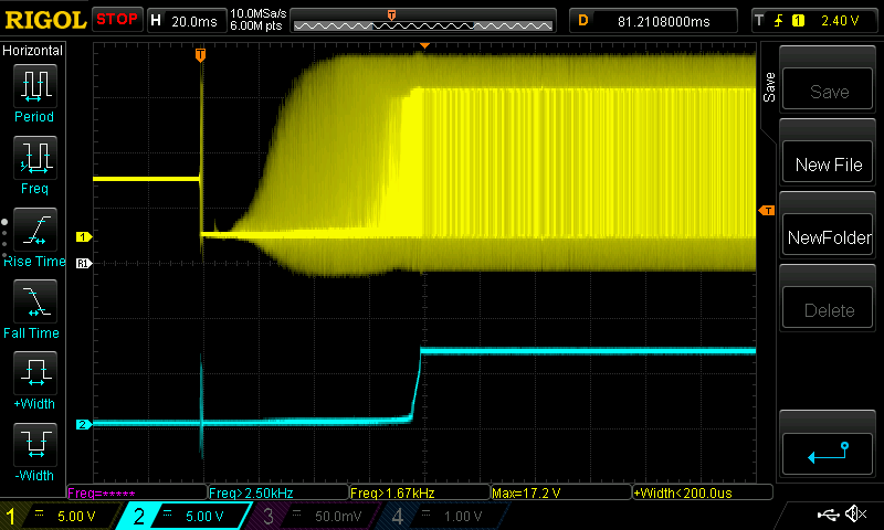
Hello, i have a problem with TAS5721 generating quite loud thump sound in the speakers when exiting shutdown mode. Board is designed according to "2.1 system" application note from the data sheet. System is in 2.1 mode, so i have removed SSTIMER cap according to the data sheet, and i'm enabling mid-Z ramp feature when exiting shutdown, by writing 0x84 to register 0x05. Still i get quite loud thump during shutdown exit (during shutdown enter after playing some sound on amp, there is only barely audible click, so the problem is only related to shutdown exit). Is there anything i could do to minimize this unwanted thump?
Thanks,

WM

  • Hi WM,
    If you already set D7 andD2 in the register 0x05 to enable mid-Z ramp and 2.1 mode, the pop noise should be low. You can also try to adapt the start/stop time in the register 0x1a to see if there is any improvement.
    In addition, did you follow the timing requirement in the Figure72 in the datasheet. Please also refer to the reference SCH design in the Figure 81 in the datasheet.
    Best regards,
    Shawn Zheng
  • Hi Shawn, yes, i have checked this twice, and i'm writing 0x84 to 0x05 to exit shutdown, which sets bits D7 and D2 during shutdown exit. I have tried to modify 0x1A, but this only delays pop noise during exit - it's still there, but it's delayed. I think that i follow timing as well. I have managed to capture signal which causes pop during shutdown exit - it's an oscillation in audible range (about 17kHz), lasting about 1ms. I'm including oscilloscope screens (signal was captured on a speaker output of L or R speaker). Maybe this will give a hint on the reason. 

    Thanks,

    WM

  • Hi WM,
    Thanks for the test. Could you please show me your SCH for TAS5721? I think the above waveform is the after indutors, right? Could you please also capture the waveform on the AMP differential output pins(before inductors)?
    Best regards,
    Shawn Zheng
  • Hi Shawn, yes, waveforms are captured after inductors. Schematic of the output stage is exactly the same as one on the page 67 of the TAS5721 data sheet (Figure 81 - 2.1 system). Only differences that i see are:

     - caps C41,C42,C43,C44 are 100uF not 220uF

     - it is possible that caps C27,C28,C29,C30 may not be of COG type (i'm not sure if the ones that i used to assemble prototype are COG's or not, i have yet to check this)

    I 'll try to capture requested waveforms directly on TAS and will post them later.

    Thanks!

    WM

  • Hi, here's comparision of waveform captured directly on an AMP output (SPK_OUTB, yellow), and on speaker output (after filtering, blue). I'm not sure if pop sound is caused by first 1 ms oscillation, or the voltage ramp which goes up after PWM gradually starts to get wider duty cycle.

  • Hi WM,
    Thanks for the measurement. Is the oscillation also shown on the other differential output pin? Could you please capture both P and N output from AMP? I don't think the oscillation is expected. Please make sure your power-down sequence is as below: mute AMP(reg 0x06)->enter shut-down mode(reg 0x05)->drive RST and PDN pins to low->remove power supply. One experiment you could do is to disconnect the load speakers and remeasure the PWM waveform on the differential output, and see if the oscillation is still there.
    Best regards,
    Shawn Zheng