This thread has been locked.

If you have a related question, please click the "Ask a related question" button in the top right corner. The newly created question will be automatically linked to this question.

TLV320AIC3104: AGC algorithm

Part Number: TLV320AIC3104
Other Parts Discussed in Thread: TLV320AIC3204,

Hi,

I have some doubts about the functionality of the AGC. We have a device which measures noise and use this codec to measure it. The way of measurement noise is reading the value of the AGC according to the quantity of noise read by the microphone, that is connected to a channel of the codec.

The register of the preamp (R19) is set to 0, the AGC is enabled and its target level is set to -24db. At first sight, every registers ared defined to obtain the maximum gain. The problem we have is that this codec is also used in other device with the same configuration of the registers, but in this case the microphone has a membrane that slightly attenuates the noise, so I would like to calibrate this measure.

The datasheet talks about the algorithm of the AGC. I guess that this algorithm fix the relation between input of the AGC ante output. Is there any way to access to this algorithm?

  • Hello,

    Most of the AGC algorithm parameters can be configured by the user. Please refer to Section 2.3.2.3 of the Application Reference Guide for details.

    In order to understand how much gain the AGC is applying, there is a read-only register (Page 0, Register 93) that can be read using i2c. The other read-only registers help identify if the AGC/ADC is saturated or if the AGC detects signals below noise floor.

    I hope this information is useful for the calibration process. Please let us know if you have further questions.

    Best Regards.

  • Hi Diljith,

    As I can see you sent me the reference guide of the TLV320AIC3204 instead of the TLV320AIC3104. Could you send me the right one? Could you specify me again the registers based on the right codec?

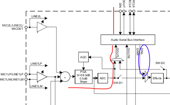
    I leave you attached a screenshot of the codec block diagram. As you can see on it the red line shows the path when the noise inputs on the codec and goes out to the microcontroller. The blue line shows the path from the microcontroller to the codec in both paths the AGC doesn´t receive any signal from the exterior so I dont understand how it is posible to define the gain in the AGC through the I2C bus.

  • Hi Denis,

    Apologies for sending out the AIC3204 information instead of AIC3104. The AGC registers for AIC3104 are described in the datasheet itself. We have not published a separate ARG. The relevant sections are 10.3.3.2.2 for AGC description and 10.6 for Register Map.

    The AGC registers are from Page 0 Register 26 to Register 35.  Register 36 is a flag register to indicate ADC/AGC saturation.

    The AGC algorithm is a feedback algorithm that monitors the ADC output and controls the PGA to maintain the ADC output at the target level. The gain that the AGC applies on the PGA can be read using I2C bus from Registers 32 and 33. 

    Please let me know if you need further information on this.

    Best Regards.