Other Parts Discussed in Thread: TLV320AIC3204
Hello,
I develop an application to sample data from a generator signal using a STM32 microcontroller and TLV320AIC3204EVM-K for Analog to Digital Converter. Here is my configuration:
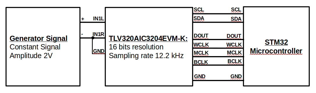
The STM32 Microcontroller works as master, so it provides WCLK, MCLK and BCLK to ADC. I use the following setup for the clock frequencies:
WCLK = 12.2 kHz
MCLK = 3.125 MHz
BCLK = 390.6 kHz
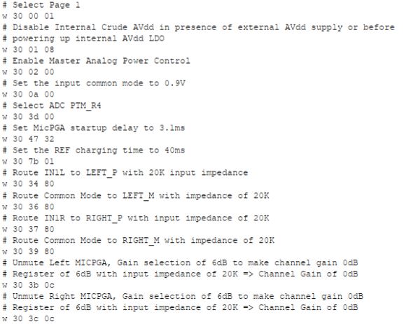
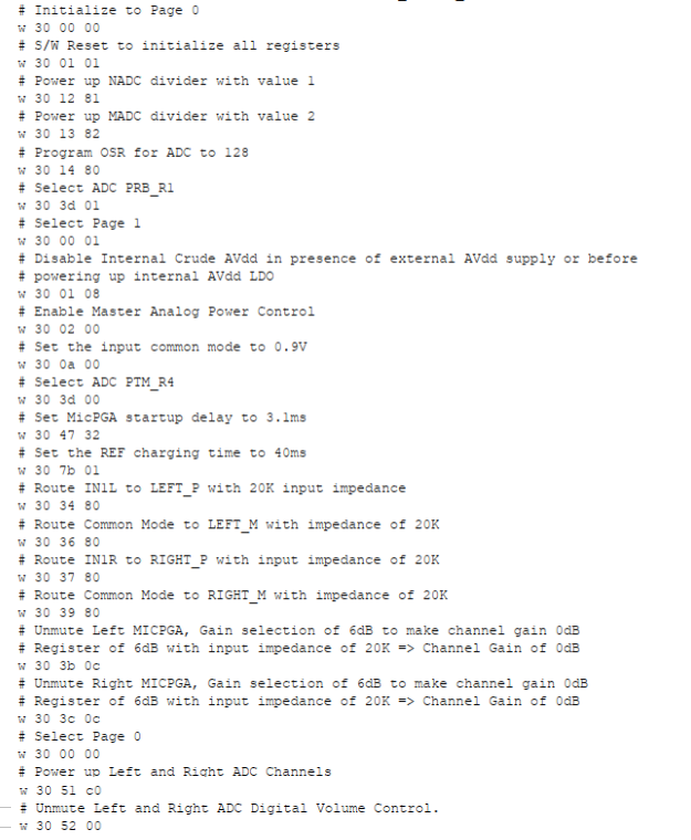
For ADC programming, I use an example code from TLV320AIC3204 Application Reference Guide:
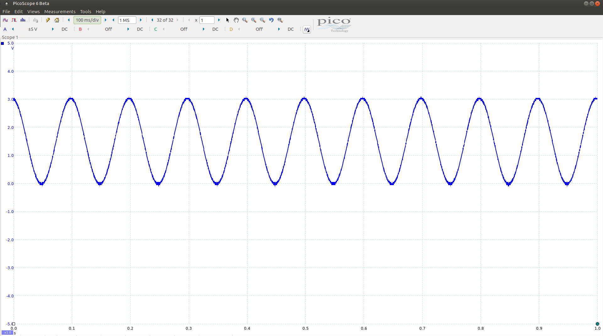
Then I observe the data sent by ADC with oscilloscope:

The blue signal is analog input signal
The green signal is WCLK
The yellow signal is BCLK
The red signal is DOUT
All the clock frequencies are OK. I also get the bit sequences for both left channel (2 V) and right channel (ground level). The problem is I do not get the correct ADC value after I decode the data. For channel 00 (2 V) the bit sequence does not represent a constant hexadecimal value (or at least it only changes a little caused by noise). For channel 01 (ground level) I always get a bit sequence of 0xFFC5 or 0xFFC4 while I expect 0x0000 sent from ADC. Could you help me to solve this issue? Or maybe you have a sample code to sample a clean signal? I think the code that I used does some filtering and some other processes that can alter the mapping from original signal to ADC value.