This thread has been locked.

If you have a related question, please click the "Ask a related question" button in the top right corner. The newly created question will be automatically linked to this question.

TAS5342LA: Output noise Problem

Part Number: TAS5342LA

Hello,

I get a very loud noisy output at the PWM outputs of the TAS5342LA when part starts getting a little bit too warm. The weird thing is, both protection signals OTW and SD stay high, but when I cool down the part with coolant spray this behavior stops. Also the IC temperature I'm measuring is around 60°C wich is way below max specs.

I designed the BTL stage as provided in SLAU243 (M1,M2,M3 = 0) All Caps close to the Chip are X7R. Roc =22kOhm.

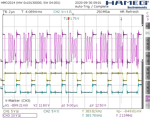
The picture below shows the two PWM inputs (Channel 1 and 2) and the TAS5342LA PWM output (Channel3) directly at the Output pin before the Filter inductor. I'm measuring with a 4Ohm load. 

Any Ideas what could cause this problem?

Thanks in advance!

  • Hi Lucas,

    Are you using a heatsink on the TAS5342LA? If so is it similarly sized as the one we use on the EVM? 

    To clarify, the oscilloscope is reading PWM_A, PWM_B, and OUT_C? 

    Best Regards,

    Robert Clifton

  • Hi Robert,

    Yes I'm using a heatsink on the Chip! No it's smaller than the one you use on the EVM.

    The oscilloscope shows PWM_A (OSC Channel 1/Yellow), PWM_B (OSC Channel2/ Blue) and OUT_A (OSC Channel 3/violet)!

    I'm wondering if its normal that the PWM output starts switching randomly (as seen in the oscilloscope picture above) when the chip is overheating? I thought at least the OTW line should be pulled low then. But this this not the case when the output starts doing this!

    kind regards,

    Lucas

  • Hi Lucas,

    Thank you for clarifying! I had to ask if you were using a heatsink because the tests you described performing (blowing coolant spray on the part) sounded as if there was no heatsink attached to the device! 

    Can you provide a schematic and part number of the inductors you are using on the output filter?

    Best Regards,

    Robert Clifton

  • Hey Robert, 

    attached you can find the schematic of the amp section. The part number of the inductors is: RFB0810-100L

    thanks for your help!

    AMP-AMP.pdf

  • Hi Lucas,

    Happy to help! 

    Depending on the output power, those inductors might not be able to handle the current draw.  5.3A max current rating means the RMS current would be at 3.74A. Using a 4 ohm and the most power you can output would be about 56W. That's not taking into consideration how the thermal rise in the inductor would affect the maximum current the inductor can handle. This could be a potential concern. 

    I noticed that your model has an extra pin labeled as EP. Is this safe to assume that it represents the thermal pad? Have you verified that the heatsink is properly grounded to the PCB board and making good contact of the thermal pad as well? The thermal pad needs to be grounded. 

    Best Regards,

    Robert Clifton

  • Hi Robert,

    I finally found time testing the design again! Yes indeed the EP pin is the thermal Pad and it wasn't grounded via the heatsink. I fixed that now but unfortunately the problem still exists!

    I tried different inductors already with higher maximum current rating but this also doesn't change anything. The amplifier even starts being noisy with no input signal applied.

    Do you have any other suggestions I could try?

    kind regards,

    Lucas


  • Hi Lucas,

    Are you saying that now the amplifier is being noise with no input signal applied? 

    There might be a general layout issue. Would you be able to send your layout to me? 

    Have you tried swapping the part out with a new one? 

    Best Regards,

    Robert Clifton