This thread has been locked.

If you have a related question, please click the "Ask a related question" button in the top right corner. The newly created question will be automatically linked to this question.

PCM1792A: IREF, VCOM, etc as it relates to output current - want to add external voltage veference.

Part Number: PCM1792A
Other Parts Discussed in Thread: PCM1796, DAC11001A, PCM4222

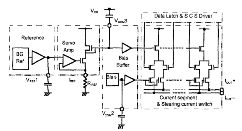
I am looking at the PCM1792A or PCM1796 as a measurement DAC. It most DACs you can drive the VCOM or VREF inputs with an external reference to create a stable output level. 

I can't find anything on the datasheet that shows the specific relationship of the output current to IREF, VCOM and VCC. 

  • Hi Al,

    Are you looking to use this as a DC voltage? We do not really characterize the VCOM and IREF voltage against the output amplitude, especially for things like output drift.

    You could consider one of our precision DACs.  The DAC11001A (and lower resolution variants) is capable of very good AC performance and un-matched DC performance.

    Thanks,

    Paul

  • No, I want to generate accurate low distortion audio signals that have a dependable output level. This is easy to do with many other audio DACs. If I set a level to 1.00V, it shouldn't be 0.98V when the temperature changes, etc.  This may not be a problem in most audio applications, but it is a problem for accurate measurements.

    High performance audio DACs tend to be good for all the other requirements. 

    In a typical voltage output DAC, Vref is usually just a filtered voltage divider that is easily overdriven externally with a voltage reference. This makes the level very stable.

    The PCM179x data sheets say very little about the relationship of Iset or VCOM etc. For example, does the Iset resistor just define an operational voltage (Iset * Rset)? 


  • FWIW, this is an excellent question.

    Awhile ago, I did a audio measurement device which talked to the host computer over USB. It enumerated as a standard USB audio device to greatly simplify the software work. Since one of the requirements was to support SPL measurement with calibrated microphones, I used a high-quality external reference with the converter (a competitor's CODEC). That worked well until the CODEC was "updated" to a rev A (or B, I forget) and the new part simply did not like an external reference. Nothing in the data sheet suggested that the external reference would not work with the updated device. Their tech support was worthless.

    Nothing in the PCM1792A data sheet indicates the actual reference value. It does say that the output current is 7.8 mA at 0 dBFS so one can infer the reference, but we're also told that the worst-case gain error is +/- 6% which is pretty terrible if the goal is to use it in a measurement device. On the ADC side, even the flagship PCM4222 has no spec on the reference tolerance.

    The suggested DAC11001A needs a proper antialiasing filter if it is to be used in a continuous-time audio sampling application. That's why the audio-specific parts are attractive -- it's all there in the one chip.

    All of this is to say that Al's request for support for a high-quality external reference is not unusual and would be welcome. Or, at least characterize the references that are on the devices!

  • Hi Al and Andy,

    I do not have a great figure to show you, but here is an approximation of the IREF and VCOM functions.

    Not that the VREF1 and VCOM2 are not actual pins on the PCM179xA devices.  The IREF resistor is part of a V/I reference, so changing the resistance value should scale the output current.  The VCOM is primarily for noise filtering.

    Thanks,

    Paul

  • Thanks Paul and Andy,

    In a measurement system we don't need absolute initial accuracy as much as stability.  We can calibrate out fixed errors.

    A bandgap suggests that the reference is probably fairly decent and stable. This sets the current along with Riref. Riref will have a temp coefficient of maybe +/- 25ppm/ C for a thin film resistor.  I don't know what the curve actually looks like for this.

    From the schematic, I can't tell what the influence of the remaining circuits will do either.

    I don't see a straightforward external trick to insure stable levels with the conversions. I have a new board designed for another purpose, that I can use as a test platform once I have it fabricated.

    I am open to suggestions.

    Thanks

    Al