This thread has been locked.

If you have a related question, please click the "Ask a related question" button in the top right corner. The newly created question will be automatically linked to this question.

TAS2110: Distortion

Part Number: TAS2110

Hi team,

My customer is evaluating the TAS2110EVM. Could you please support the following question?

To determine the configuration parameters, I connected the speakers to the TAS2110EVM and used PPC3 to output the audio from the PC, and it seemed to be audibly distorted.
(When I output a 1 kHz signal from the PC and measure it with Audio Precision, it's about 30% THD)

To improve the distortion, I have adjusted various parameters of EVM with PPC3, but the audible distortion is not improved.
Also, I have an 8ohm speaker connected, but it cannot output more than 2W even at vol 0dB.

I believe the D2S Filter listed on page 18 in the datasheet is only to be used during measurements, is that correct?

This is a parameter dumped from EVM with PPC3.

/cfs-file/__key/communityserver-discussions-components-files/6/TAS2110.txt

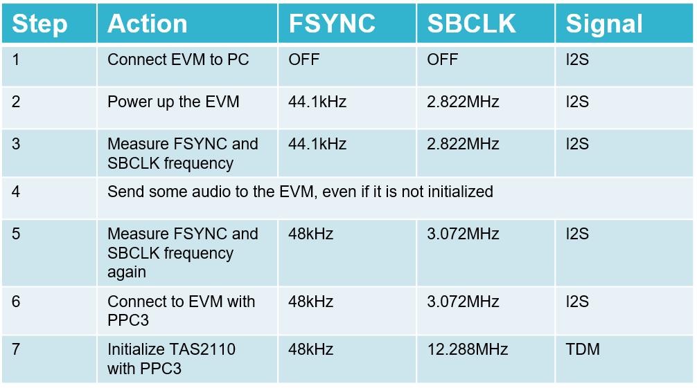
When I checked the error information, it seems to be TDM Clock Error. When this error occurred, I was inputting an audio signal to the EVM via USB from the PC and setting AUTO_RATE in the TDM Config to 0b (Enable) in the GUI.

Then, when I observed the I2S / TDM signal of EVM with an oscilloscope, it was audio data = I2S, Sample rate = 48kHz, FS_RATIO = 64, so disable AutoRate of TDM Config and manually set the value corresponding to the above I2S. However, the distortion did not improve. Also in this case, the TDM Clock Error display of IRQZ became red.

Is it a problem with the USB driver installation failing, etc.?
I remember being asked to install Visual Studio, Matlab, etc. when installing the driver, but I am not able to install Matlab at this time.

Regards,

Yamaguchi

  • Hi, Yamaguchi-san,

    Our team will take a look at this information and will provide a response as soon as possible.

    Best regards,
    Luis Fernando Rodríguez S.

  • Hi Yamaguchi-san,

    The default settings from PPC3 GUI should match the data source from the EVM processor, in other words, there should be no clock error if using USB audio source with default PPC3 settings.

    By any chance, do you have a second board you can try?
    Can you please share a picture of your board to verify all the jumpers are setup correctly? All headers should have jumper inserted expet for:

    • J8
    • J12
    • J14

    Sometimes the FSYNC and SBCLK signals change when there the PC sends audio over USB. these clocks should be FSYNC = 48kHz (single bit) SBCLK = 12.288MHz.
    Please try the below procedure:

    • Connect EVM to PC
    • Power up the EVM
    • Measure FSYNC and SBCLK frequency
    • Send some audio to the EVM, even if it is not initialized
    • Measure FSYNC and SBCLK frequency again

    Best regards,
    -Ivan Salazar
    Applications Engineer - Low Power Audio & Actuators

  • Hi Ivan-san,

    Thank you for your support. 

    Customer mentioned that they hadn't change the jumper setting from the default setting.

    • Not inserted for J8/J12/J14
    • Inserted J3 to J6, J9, and J11 (1-2 pin connected)
    • Inserted J7 and J13

    Sorry I cannot share the picture.

    FSYNC and SBCLK were as follows. Is this the correct state?

    I have additional question.

    If the input signal is I2S, could you tell me the registers and setting values that need to be changed from the default setting?
    (Fsync=48kHz).

    Regards,

    Yamaguchi

  • Hi, Yamaguchi-san,

    Thank you for the information you provided. We will analyze the information and will come back with some suggestions based on it.

    Best regards,
    Luis Fernando Rodríguez S.

  • Hi Yamaguchi-san,

    TAS2110 TDM interface is only checking for one transition on the FSYNC signal, so it does not actually matters if FSYNC signal is 50-50% or a single bit.

    Could you please try to change the following settings to check if it improves the sound:

    • Edge polarity
    • Frame start polarity
    • Receiver offset

    In the meantime, I'll setup some instructions to reprogram the processor on the EVM and will send to you.

    Best regards,
    -Ivan Salazar
    Applications Engineer - Low Power Audio & Actuators

  • Hi Ivan-san,

    Thank you for your support.

    I received the feedback from the customer.

    • Edge polarity : No change
    • Frame start polarity : worse
    • Receiver offset : worse

    As a confirmation, looking at the data sheet, each characteristic is a measured value under a load that assumes the inductance of the speaker, such as 8ohm + 30uH or 4ohm + 30uH. If this inductance is 30uH or more, is there a possibility that problems such as distortion will occur?
    (When I measured the speaker I am currently using with an LCR meter, it was Ls = 350uH at 1kHz.)

    Regards,

    Yamaguchi

  • Hi Yamaguchi-san,

    If possible, please share scope shots of the output waveform, please use LC low-pass filter for measurement.

    You could also try different speakers, but I don't think the distortion would be related to the speaker. Would you be able to test the device by sending TDM signals from a different source? Like AP system or similar?

    Best regards,
    -Ivan Salazar
    Applications Engineer - Low Power Audio & Actuators

  • Hi Ivan-san,

    Thank you so much for your support. I will close this thread because the issue has been resolved. 

    The customer said that they had used a D2S filter (self-made) with an op-amp for the measurement, but there seemed to be a problem with this design.
    After reviewing the filter design, they were able to improve the THD to about 1%.
    They are going to review the measurement system a little more.

    Although there is still some audible distortion, the waveform after passing through the D2S filter is a clean sine wave, so customer believes that the IC is operating normally.

    I will post a new thread when I have further questions from customer.

    Regards,

    Yamaguchi