This thread has been locked.

If you have a related question, please click the "Ask a related question" button in the top right corner. The newly created question will be automatically linked to this question.

LMK04806: 0-delay mode have some problem

Part Number: LMK04806

Hello, there are some problems in the 0-delay mode of LMK04806 during the debugging recently. I hope the original factory can help. The specific problems are as follows

R0 (INIT)	0x80160140
R0	0x00145000
R1	0x00145001
R2	0x00140082
R3	0x00142803
R4	0x00140284
R5	0x00140145
R6	0x61610006
R7	0x11110007
R8	0x11110008
R9	0x55555549
R10	0x91425CAA
R11	0x4008100B
R12	0x130C006C
R13	0x2302800D
R14	0x0200000E
R15	0x8000800F
R16	0xC1550410
R24	0x00000058
R25	0x02C9C419
R26	0x8FA8001A
R27	0x0000041B
R28	0x0050041C
R29	0x0200005D
R30	0x0100015E
R31	0x001F001F

1. In non-0-delay mode, if single PLL2 is used, the clock output is normal according to the design value, which has been adjusted.So the hardware circuits should be fine.However, in 0-delay mode, there is no clock output, and the interface of register setting (see the register table in the attachment) is as follows

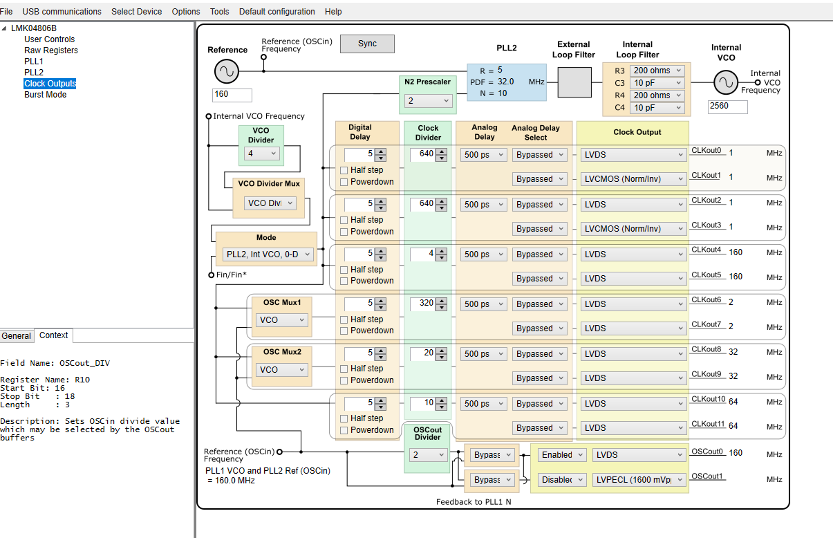
Our assessment should be the register setting or sync signal status (always high) is wrong, resulting in no output of the clock, can the manufacturer help to check?Or give an example of register Settings using single-PLL2 0-delay mode?

  • Hello Gabriel,

    When using zero-delay mode, you should set PLL2_N_CAL to the value that would normally be used for the N-divider if not in zero-delay mode. So set PLL2_N_CAL = 10, and PLL2_N = 2 instead. If this configuration change is not made, the VCO will calibrate incorrectly and may not be able to lock.

    Next, I see that the SYNC_MUX is set to a reserved state. This should be programmed to a non-reserved state. Setting SYNC_MUX active low with SYNC_TYPE set to input w/ pull-up will typically prevent a permanent SYNC event.

    Try these steps first, and let me know if further assistance is required.

    Regards,

    Derek Payne

  • Dear Derek

    Thanks for your replying!

    but ,it has been changed according to the original factory reply, but PLL is still in the lockout state, and there is no clock output.

    Want to ask, can the original factory give a single PLL2 0-delay example?Or we can provide input reference clock frequency and output clock frequency information, they can help configure it?

  • Gabriel,

    Please try the attached file, with the modifications I outlined. The GUI appears to have trouble representing the zero-delay condition, and so the internal VCO frequency shows 128MHz instead of 2560MHz, but the configuration should still be valid.

    LMK04906 ZDM example.tcs

    Regards,

    Derek Payne

  • Dear Derek

    I have tried the example replied by TI's original engineer. There is a clock output, but the frequency of the output clock is not accurate, and PLL cannot be locked.

    1. I wonder if the bandwidth setting of the external loop filter is not reasonable: BW=240kHz, phase margin =70°.

    2. Does sync signal affect PLL lock status in zero-delay mode?When debugging the non-zero delay mode, it was found that when SYNC was low, the clock had no output.

    3. I read in the specification that it is recommended to use absolute dynamic delay in zero delay mode. Will this cause PLL to fail to lock?

    4. Another puzzle to me is that the bandwidth of PLL loop filter is generally 1/10-1/100* phase detection frequency, but the tool provided by TI seems not to be like this.For example, when the phase detection frequency is 32MHz, TI's clock design tool (as shown in the figure below) recommends a loop filter bandwidth of around 150kHz, about 1/200.

    Hope the original engineer can answer, and preferably can verify the correctness of the example on the evaluation board.After all, sometimes with too many variables, it's hard to find a problem.

  • Dear Derek.

    Ctm is already solve this question ,many thanks for your reply!