This thread has been locked.

If you have a related question, please click the "Ask a related question" button in the top right corner. The newly created question will be automatically linked to this question.

LMX25311226EVAL: Device Activation

Part Number: LMX25311226EVAL
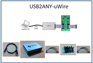
Hi,
I have the LMX2531 Evaluation board (i have 1126 and 1226).

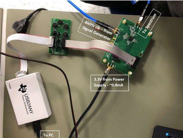
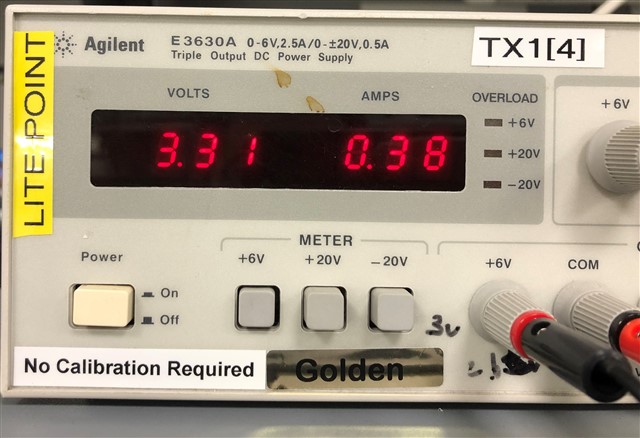
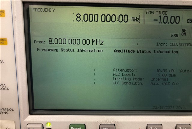
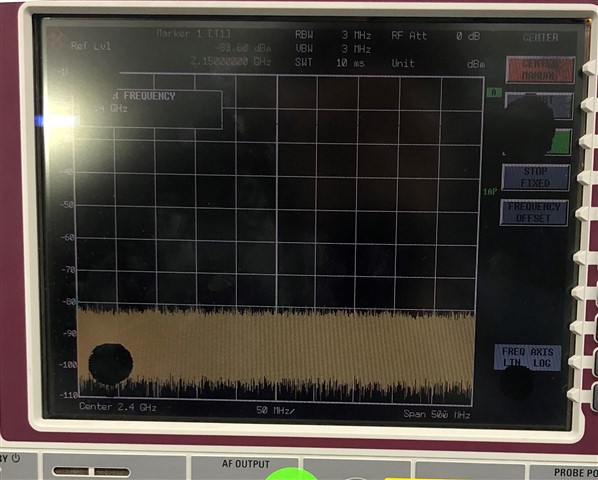
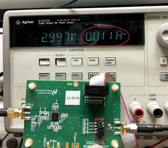
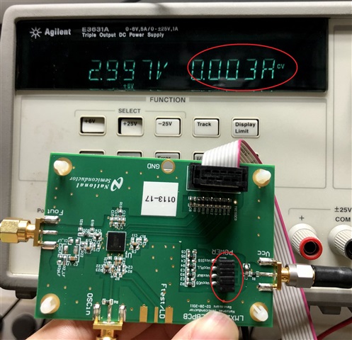
The board connection configuration is: 3.3V in the VCC SMA, 8MHz clock in the OSCin SMA, and Fout SMA to the spectrum.

I check the following guides:
- https://www.ti.com/lit/ug/snau077a/snau077a.pdf
- https://www.ti.com/lit/ug/snau083a/snau083a.pdf

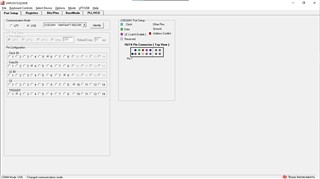
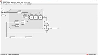
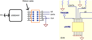
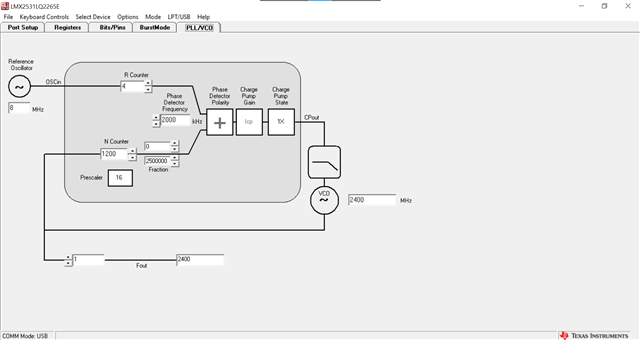
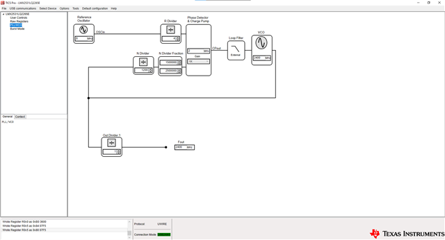
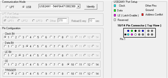
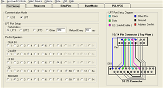
^Both guides above show that you only need to connect the device via the USB2ANY, run the CodeLoader, and then config the frequency thru the PLL tab.
After this sequence, I can't see anything in the spectrum.
Should I config some registers? or active some fields? run any flow?

The CodeLoader screenshots are attached.

Thanks,
Avihu.

  • Hi Avihu,

    Do you have the USB2ANY-uWIRE adapter board as mentioned in Appendix C of the user's guide?

  • Hi Noel,
    Yes I connect the USB2ANY to the computer (USB) and to the LMX2531 EVALUATION board (10 pin cable).

    The CodeLoader identify the USB2ANY (blinking when pressing the identify button).
    Then, I select my device type and configure the frequency settings.

    Nothing happened.

  • Hi Avihu,

    CodeLoader blinks because it can identify the USB2ANY but not the EVM.

    The EVM will not work if you connect USB2ANY directly, you must have the USB2ANY-uWIRE adapter to bridge USB2ANY and the EVM.

    Do you have the adapter board?

  • Hi Noel,
    its probably it...

    I dont have the adapter board.. its shouldn't came with the EVM board?

    what can I do now?

    there is another way to active the device?

  • Hi Avihu,

    Without the adapter board, we have to manually wire them together. Below is the pin assignment.

  • Hi Noel,

    I get one of the adapter boards.

    still, I cant see the output signal after the configuration that described in the manual.

    i attaching the setup, maybe you will se some problem.

    maybe there is another configuration that need to be set in the code loader?

  • Hi Avihn,

    In the Bits/Pins page, if you uncheck the CE box, do you see a current drop?

    Similarly, if you check the REG_RST box, do you see a current drop?

    if noting happen, then I guess your adapter board was not configured properly. See Appendix C of the user's guide for how to setup the jumpers for LMX2531.

    BTW, I recommend you use TICS Pro instead of CodeLoader to control the board, CodeLoader has already been faded out.

  • Hi Noel,
    i move to TICS now.

    still, nothing....

  • Hi Avihn,

    What were the results of the current tests?

  • Hi,

    no change ~0.4A

  • Hi Avihu,

    0.4A is not correct, this device won't consume this amount of current, typical operation current is just 40mA.

    I noticed that your supply voltage is not right, it should be 3.0V. If you still see 0.4A with a 3V supply, I think your board has problems. Remove the power supply jumpers one by one to see which power supply path has problem.

    In addition, the slew rate of a 8MHz, -10dBm sine wave signal is going to be very bad. -10dBm is also below the specification requirement. Make it +10dBm to increase the slew rate. BTW, the phase noise of a 8MHz signal from a signal generator is bad, there is no surprise that the output from LMX will has bad phase noise too.

  • Hi Noel,
    i change now to 8MHz signal with +10dBm.
    the current consumption is ~11mA, and when the "VccDIG" pins is jumperd the current drop to ~2mA.

    I try various consolation of the jumpers but still I don't see the desire signal in the spectrum.

    there is any setting that I need to configure? in the EVM or / and the TICS ?

  • Hi Avihu,

    With all the jumpers, after Vcc power up, is the current equal to 3mA? What was the reason that it was 0.4A?

    Alright, now, what is the voltage at the CE pin? A min. of 1.6V is required in order to consider it is a logic HIGH. In TICS Pro, check the CE box to make CE pin high.

    If you get 11mA after CE pin is HIGH, then check the REG_RST box to reset the device. If you can see a current drop, then the communication between TICS Pro and the EVM is through. If you see nothing change, probe the DATA, CLK and LE pin to check if the waveforms are looking good. 

  • Hi Noel,
    the CE pin shows ~3.3V.
    after check the REG_RST the current drop from 11mA to 0mA.

    so the communication is OK?

    still, nothing on the spectrum...

    attaching the pins map (screenshot from CodeLoader4, didn't know how to config in TICS)

  • Hi Avihu,

    If you set LOCK DETECT FoLD to Logic High Output, what is the voltage at Ftest/LD pin? This is the final test of the communication.

    However, from your diagram above, looks to me that your communication is not going to work. The default pin assignment should be

    Please probe the uWire signals to ensure the waveforms are correct. 

  • Hi Noel,
    i want to update that i succeed to get my signal Slight smile

    one last question:
    the EVM have to be connected to the PC? 
    i mean, cant i just configure the PLL and after that unplug the u-wire?

    if i do that now the signal is shunting down.

  • Hi Avihu,

    if the CE pin is tied to Vcc on the EVM, after programming, you can remove the ribbon cable without issue.

  • Hi,
    Great - its work.

    there is a way to config that the device will automatically config to the last setting every power up?

  • Hi Avihu,

    There is no non-volatile memory in the LMX2531.  You would have to use an external micro-controller like the MSP430 to program on start-up. 

    The CDCM6208 has an MSP430 example for programming SPI into the CDCM6208.  This could be adapted for the LMX2531.

    See AppNote on MSP430 as bootloader for CDCM6208.  Also see CDCM6208 sw files for app note
    This is from the CDCM6208 product folder.

    73,
    Timothy