This thread has been locked.

If you have a related question, please click the "Ask a related question" button in the top right corner. The newly created question will be automatically linked to this question.

LMK04828: Multi-boards LMK CLKOUT Synchronization

Part Number: LMK04828

Hi,

We are planning to use LMK04828 Clock Synthesizer(Master and Slave scheme) to RFSoC FPGA multi-board synchronization.

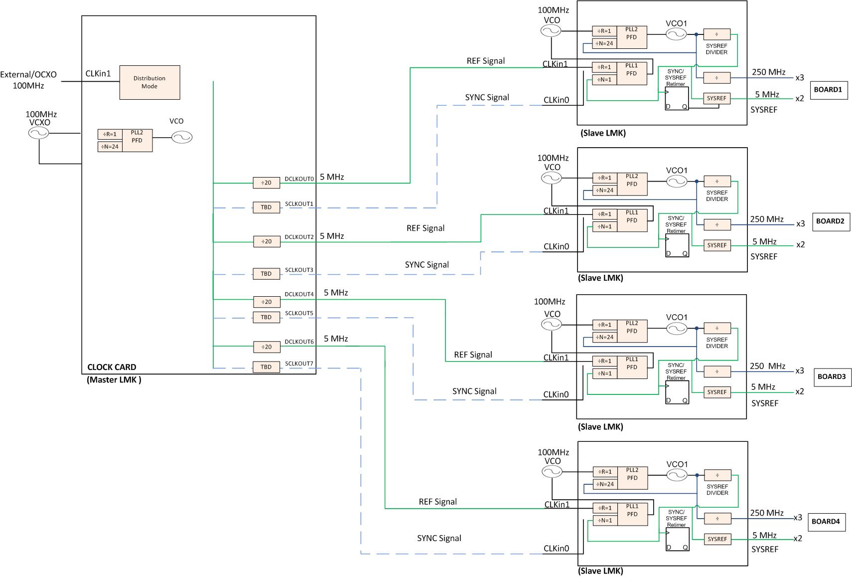
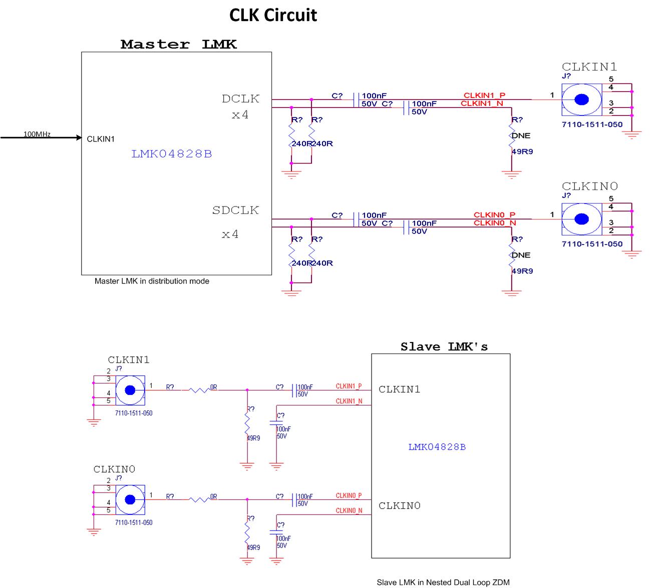
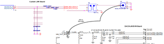
  • The Master LMK will have reference clock of 100MHz at CLKIN1 from external/on board OCXO(optional).
  • The Master LMK will be in distribution mode, and generating 5MHz of reference clock for the Slave LMK's.

  • All the slave LMK's will receive reference clock of 5MHz at CLKIN0 from Master LMK& will be through matched cables.
  • All the Slave LMK's will have 160MHz VCXO input to OSCIN
  • Slave LMK's will be generating 160MHz DCLKOUT and 5MHz  SYSREF to follow the ZDM and in Dual loop mode.
  • All 4 slave LMK output clocks need to be synchronized and aligned for Multi-clock synchronization.

Please verify the below scheme and confirm that All the slave LMK will have deterministic latency from power on to power on. 

We will share configuration files.

LMK Multi Clock Synchronization scheme.pdf

  • Hi,

    Your clock tree architecture looks good and you should use the secondary (slave) LMKs in nested loop dual PLL 0-delay mode, to achieve the synchronized clocks outputs.

    There is an app note on the multi-clock synchronization, which could help you to understand the conditions for the 0-delay mode synchronization.

    I would be suggesting to have an additional sync option also in your architecture (other than 0-delay mode), where you provide the primary (master) LMK's SYSREFs output to secondary LMKs CLKin0 input as sync option and keep 5MHz input to CLKin1 input. This can provide some more flexibility to your clocking architecture.

    Thanks!

    Regards,
    Ajeet Pal

  • Hi Ajeet,

    Thanks for you feedback,

    1. If we connect the master LMK's SYSREF path to CLKin0 as a synchronous path, should we set the slave LMK to reclock mode?

    2. Since Master LMK is in Distribution mode,Do we need to write a sync divider register to align all of the clock outputs  ?

    3.Due to hardware constraints, all output from the master LMK (5 MHz) to the CLKin0 of the Slave LMK is routed via SMA connector and matched cable,      

    •  Implying that the CLKin 0/1 input is CMOS or bipolar. So, how do we convert the Primary LMK differential output to a single ended signal that can be fed   to  the slave LMK CLKin 0/1 via SMA connector?
    • What effect will the change have on the phase noise and  synchronization of all slave LMK outputs?


  • Hi e2e.ti.com/.../4455066

    Awaiting for your feedback

  • Hi Lakshminarayana,

    Sorry for the delay in response.

    1. If we connect the master LMK's SYSREF path to CLKin0 as a synchronous path, should we set the slave LMK to reclock mode?

    Yes, CLKin0 can be used for SYNC input and if needed for SYSREF re-clock mode also.

    2. Since Master LMK is in Distribution mode,Do we need to write a sync divider register to align all of the clock outputs  ?

    To align all dividers output in primary (master) LMK, you would need use the sync and it will reset all divider, which in turn align all outputs.

    SDCLKoutX used the common SYSREF divider for SYSREF frequency and it would be value 20.

    3.Due to hardware constraints, all output from the master LMK (5 MHz) to the CLKin0 of the Slave LMK is routed via SMA connector and matched cable,      

    •  Implying that the CLKin 0/1 input is CMOS or bipolar. So, how do we convert the Primary LMK differential output to a single ended signal that can be fed   to  the slave LMK CLKin 0/1 via SMA connector?
    • What effect will the change have on the phase noise and  synchronization of all slave LMK outputs?

    You doesn't need to convert single ended and can provide differential through length matched cables. CLKin0 required DC coupled input, if used as SYNC.

    As you are feeding input at CLKin1 as reference in nested loop dual PLL mode, it's phase noise performance depends on the 160MHz VCO.

    Thanks!

    Regards,

    Ajeet Pal

  • Hi e2e.ti.com/.../4455066

    Thank you for your response.

    1. We can only give single ended input to clkin0/1 due to hardware constraints, so we wanted to know how to convert differential to single ended on the       primary LMK?

    2. Assuming we can provide a single ended clock to clkin0/1, do we need to convert to differential via balun on the slave LMK board?

    3. We were attempting an experiment in which we fed the LMK04828 output (LVPECL 122.88MHz) which is converted to single ended via balun as shown in image to Clkin1 of the DAC38J92EVM board. The images  attached shows the connection between boards .
    We were unable to lock PLL1, but we were able to lock using a sine wave source from extenal to the same Clkin1 input of DAC38j92EVM. why?

  • Hi Lakshminarayana,

    You need to be ensure, primary LMK output is stable, before giving to the secondary LMK. Also check the amplitude level before feeding to secondary LMK.

    Would be great, if you can able to share the both LMK config files for have a look the settings.

    Thanks!

    Regards,

    Ajeet Pal

  • Hi Ajeet pal,

    We will share the configuration files.

    We have checked the Amplitude level, it's above 600mVpp.

    . We can only give single ended input to clkin0/1 due to hardware constraints, so we wanted to know how to convert differential to single ended on the       primary LMK?

    Can you reply to this?

  • Hi Lakshminarayana,

    We have checked the Amplitude level, it's above 600mVpp.

    With the shown measured amplitude, you can go ahead with the single ended input to CLKin1 for PLL lock.

    As mentioned above, if you are going for SYNC using CLKin0 input to the secondary LMK, it should be differential DC coupled input.

    Thanks!

    Regards,

    Ajeet Pal

  • Hi

    Please verify the below clocking scheme for Multi Board LMK synchronization,

    Due to hardware constraints, we will use single ended input to Slave/Secondary LMK, as previously stated. Please verify the clock circuit for converting differential to single ended clock.

    Thanks.

  • Hi / Team,

    Awaiting for your feedback.

  • Hi Lakshminarayana,

    While using the secondary LMKs in true ZDM conditions, you should get the in-phase clocks out from these devices without external sync also. 

    But for re-clocked SYSREF input (CLKin0) or external sync (for some other configurations), CLKin0/SYNC input should be DC coupled, which needs to be modify in your circuits and maintain the required pk-pk amplitude.

    Thanks!

    Regards,

    Ajeet Pal