This thread has been locked.

If you have a related question, please click the "Ask a related question" button in the top right corner. The newly created question will be automatically linked to this question.

LMK04832: PLL does not lock with VCOCXO as External VCXO

Part Number: LMK04832

Hello Team,

We are attempting to use a VCOCXO as the External VCXO reference for our dual loop PLL; however, we cannot get a lock with our current design.

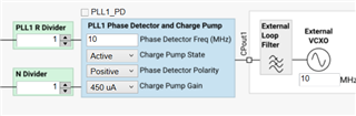
The 10MHz VCOCXO we are using has a control voltage range of 0-5V resulting in a +/-4Hz deviation. We have designed an amplifier to take the 3.3V output of the LMK04832 to drive the 0-5V requirement of the VCOCXO.

Is there something we are missing in configuration or loop-back filter that would result in the PLL never locking?

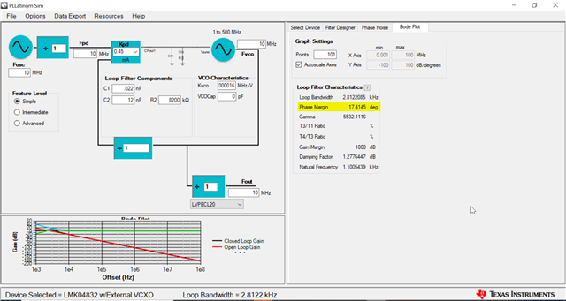
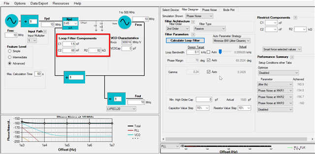
I have attached our TICS configuration & loop-back filter simulation.

OCXO.tcs

Thanks,

Grant

  • Hello Grant,

    Unfortunately, because the PLL is controlled via a voltage, an OCXO (which does not produce a voltage) cannot feed back a voltage to the PLL, and therefore, cannot force the PLL to go into lock. To use the LMK04832, you would need to use a VCXO. To better understand your use case, why are you trying to use an OCXO?

    Thanks,

    Andrea

  • Hi Andrea,

    Thanks for the quick reply!

    We are using an VCOCXO to reduce the jitter coming out of the PLL, we had done the initial design with a VCXO but could not get the jitter low enough.

    The VCOCXO has a 2Vpp output clock which we have connected to the OSCin of the PLL, which feeds the second stage of the dual loop PLL and are using the CPout1 to drive an amp that is connected to the ECF pin of the VCOCXO. Can you expand further on why this won't work?

    Thanks again for the help!!

  • Hello Grant,

    It will work, I misunderstood how the op-amp was being used. To help you further, can you tell me a few things:

    1. Can you measure the voltage that's being inputted to the OCXO (Vtune)? Is the voltage a constant value or is it changing?

    2. What is the required voltage by the OCXO/Can you attach the data sheet of the OCXO you are using?

    3. What jitter requirements does your system have?

    4. What is the application of the LMK04832? How is our part used in your system?

    Thanks,

    Andrea

  • Hi Andrea,

    Here is the additional info you requested:

    1. Voltage output of the PLL is changing. Typically starts at 1.6V then adjusts to 30mV or 3.2V
      1. OP-Amp provides 1.5 multiplier therefore Vtune starts at 2.4V then adjusts to 45mV or 4.8V
    2. Voltage required for tuning is 0-8.5V --> +/-6Hz non-linear adjustment.
    3. Single digit nanoseconds
    4. We are using the PLL to generate 100MHz & 125MHz signals that are phase aligned to a reference 10MHz signal.

    Thanks,

    Grant

  • Hello Grant,

    Based on your Vtune values, it seems that the charge pump is leaking current, which is undesirable; however, to ensure this is correct, could you send me a picture of the signal being produced from that same pin?

    For reference, the cause of leakage current comes from not having a high enough impedance right after the node of your Vtune (which in this case is the input to the op-amp). This lower impedance does not "block" the current coming from the charge pump into the OCXO, which leads to the components of your loop filter not receiving enough current and not charging up the capacitors properly which leads to the PLL block to not function properly. Therefore, to fix this problem, you can either increase the charge pump (which will also increase your phase noise) or increase the PFD frequency (which lowers phase noise).

    Also, how much jitter are you trying to decrease by using an OCXO instead of the VCXO you were using before? How much jitter was the VCXO giving you?

    Thanks,

    Andrea

  • Hi Andrea,

    I have attached the output of CPout1 as requested, the signal varies between 1.5V and 0V occasionally (a few times a second) and is 0V otherwise. This was measured on the CPout1 pin, before the loop-back filter.

    Thanks for the explaining the cause of the leakage current. We attempted to increase the PFD to 10MHz as seen below, this resulted in the CPout1 signal being held at 1.5V without the signal variance seen in the 1MHz implementation. However, we are still unable lock to the signal.

    In the VCXO design we seeing three-digit nanosecond jitter, so we are trying to reduce our jitter by a factor of 100 with the VCOCXO.

    Thanks,

    Grant

  • Hello Grant,

    Thank you for all that information. When you changed the PFD, did you also change your loop filter values? If you didn't, this is why your PLL is not locking. I ran the simulation in PLLatinum Sim with the new PFD and you previous loop filter topology and the phase margin is 17 degrees, which makes your loop filter unstable and unable to lock the PLL.

    Instead, I would suggest for your loop filter to have the following values:

    The loop filter is dependent on the PFD, loop filter components, charge pump, and Kvco; therefore, when you increased the PFD (and if you kept your loop filter the same) that led to lowering your phase margin and making the loop filter unstable.

    Also, if this does not work, I would suggest you look into using a DPLL instead of the LMK04832 or looking into a better performing VCXO. It will also serve as a jitter cleaner and clock generator but does not require the use of a VCXO. Based on your application, I would recommend the LMK5B33216. It has low jitter output and can generate the output frequencies you need. Still do let me know if this solution does not lock your PLL.

    Good Luck,

    Andrea