This thread has been locked.
If you have a related question, please click the "Ask a related question" button in the top right corner. The newly created question will be automatically linked to this question.
Hi,
I am currently working on the LMX2594PSEVM board and am having problems synchronizing the two PLL's externally.
For testing purpose I use TICS to control the PLL's. To messure the phasedifference between the two Signals I use a VNA (www.rohde-schwarz.com/.../1EZ82).
The two PLL's are both locked and working fine. The settings in TICS are as follows:
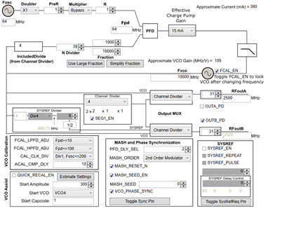
From the datasheet, I read that these settings fall under SYNC Category 3 for this use case.
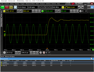
But I get a strange behavior, when I send the SYNC pulse multible times (Setup- and Hold-time are above 3ns... so basically okay). Based on my current understanding, the phase relationship of the two output signals should not change when I send the pulse multiple times. However, that is exactly what is happening. In the current settings, there are two angles that (seemingly) change randomly. For example, like this:
1. Pulse: 43°
2. Pulse: 43°
3. Pulse: 36°
4. Pulse: 43°
5. Pulse: 36°
6. Pulse: 36°
...
For my use case, I require a fixed phase relationship of the PLLs after the SYNC.
Did I do something wrong with the TICS settings or did I misunderstand the whole sync feature?
Many thanks
Thomas
Thanks for your reply, but unfortunately increase the MASH_RST_COUNT value doesn't help.
In the actual configuration I am using only the eval board. The SYNC-Pulse is also set over TICS.
I know sometimes the setup- and holdtime is under the min, but this doesn't affect my problem.
Even when the Timing is 10 times good (checked with scope) , the output phase switch between two values randomly.
My complete Registermap is in the 2500MHz_V2 textfile.
R112 0x700000 R111 0x6F0000 R110 0x6E0000 R109 0x6D0000 R108 0x6C0000 R107 0x6B0000 R106 0x6A0000 R105 0x690021 R104 0x680000 R103 0x670000 R102 0x660000 R101 0x650011 R100 0x640000 R99 0x630000 R98 0x620000 R97 0x610888 R96 0x600000 R95 0x5F0000 R94 0x5E0000 R93 0x5D0000 R92 0x5C0000 R91 0x5B0000 R90 0x5A0000 R89 0x590000 R88 0x580000 R87 0x570000 R86 0x560000 R85 0x550000 R84 0x540000 R83 0x530000 R82 0x520000 R81 0x510000 R80 0x500000 R79 0x4F0000 R78 0x4E016F R77 0x4D0000 R76 0x4C000C R75 0x4B0840 R74 0x4A0000 R73 0x49003F R72 0x480001 R71 0x470081 R70 0x4686A0 R69 0x450001 R68 0x4403E8 R67 0x430000 R66 0x4201F4 R65 0x410000 R64 0x401388 R63 0x3F0000 R62 0x3E0322 R61 0x3D00A8 R60 0x3C0000 R59 0x3B0001 R58 0x3A1001 R57 0x390020 R56 0x380000 R55 0x370000 R54 0x360000 R53 0x350000 R52 0x340820 R51 0x330080 R50 0x320000 R49 0x314180 R48 0x300300 R47 0x2F0300 R46 0x2E07FC R45 0x2DC0DF R44 0x2C1FA2 R43 0x2B03E8 R42 0x2A0000 R41 0x290000 R40 0x280000 R39 0x273E80 R38 0x260000 R37 0x258204 R36 0x240027 R35 0x230004 R34 0x220000 R33 0x211E21 R32 0x200393 R31 0x1F43EC R30 0x1E318C R29 0x1D318C R28 0x1C0488 R27 0x1B0002 R26 0x1A0DB0 R25 0x190C2B R24 0x18071A R23 0x17007C R22 0x160001 R21 0x150401 R20 0x14F848 R19 0x1327B7 R18 0x120064 R17 0x11012C R16 0x100080 R15 0x0F064F R14 0x0E1E70 R13 0x0D4000 R12 0x0C5001 R11 0x0B0018 R10 0x0A10D8 R9 0x090604 R8 0x082000 R7 0x0740B2 R6 0x06C802 R5 0x0500C8 R4 0x040A43 R3 0x030642 R2 0x020500 R1 0x010808 R0 0x00641C
Addendum: My settings work fine for other frequencies. Only the dividers and Fref were changed:
FOUT: 2500, Fref: 64, N: 39, NUM: 1, DEN: 16, CD: 4 (NOT WORKING)
FOUT: 6000, Fref: 64, N: 46, NUM: 7, DEN: 8, CD: 2 (WORKING)
FOUT: 200, Fref: 32, N: 50, NUM: 0, DEN: 1, CD: 48 (WORKING)
Thomas,
The phase SYNC will synchronize the dividers consistently. However, you are seeing about 6 degrees of variation, which works out to about 7 ps at 2.5 GHz output. Note that when you calibrate, the calibration state could be different.
I suspect that if you read back rb_VCO_CAPCTRL from the 36 degree and 43 degree state you might find that you get two different values. We have considerable overlap in these capacitor codes to ensure this.
On page 22 under the section "7.3.14 Fine Adjustments for Phase Adjust and Phase SYNC", it mentions that there is about 10 ps variation due to this.
If you want to eliminate this variation, you need to use full assist calibration.
Thank you Dean,
You are right with your assumption of the cause. Unfortunately I can't find any detailed info for the full assist mode. How do you determine VCO_CAPCTRL and VCO_DACISET ? Is there also a formula for it like for VCO_CAPCTRL_STRT and VCO_DACISET_STRT in partial assist calibration?
I have also tried the partial assist mode. This has also already solved the problem (at least with my current settings).
Hi Thomas,
Before you can "apply" full assist. you need to build a look up table by doing VCO calibration for all the frequency of interest. After each calibration, you can read back VCO parameters, i.e., VCO_CAPCTRL, VCO_DACISET, VCO_SEL.
When you apply full assist, enable all _FORCE bits, use the LUT to get the required VCO parameters for the frequency you are going to lock.
For details, please read https://www.ti.com/lit/pdf/snaa336.