This thread has been locked.

If you have a related question, please click the "Ask a related question" button in the top right corner. The newly created question will be automatically linked to this question.

LMK04821EVM: LMK04821EVM configuration issue

Part Number: LMK04821EVM
Other Parts Discussed in Thread: LMK04821, LMK04828, LMK04228

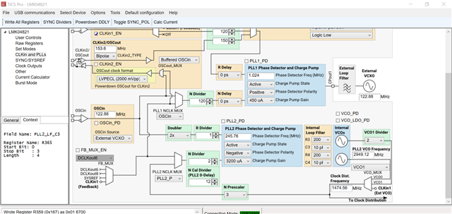
LMK04821EVM  默认配置(如图1所示)下PLL2无法锁相(Status_LD2 不亮),输出时钟频率不正确

图1:

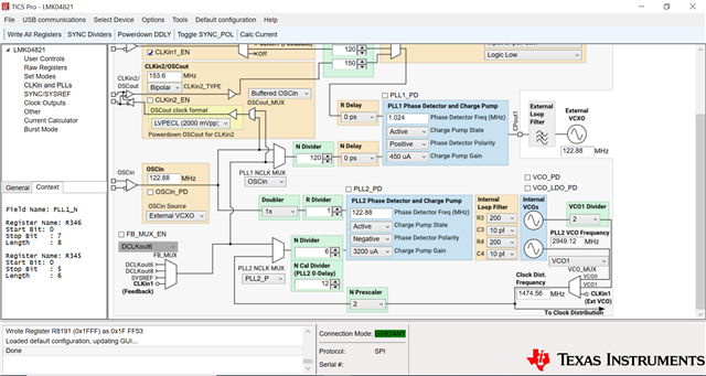
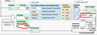
修改N Divider和N prescaler可以实现锁相(Status_LD2 亮,输出时钟频率正确可调),但VCO1 输出频率已经超出Datasheet范围,PLL2的锁相频率fpd2也不满足手册要求,配置如下图2所示:

图2:  

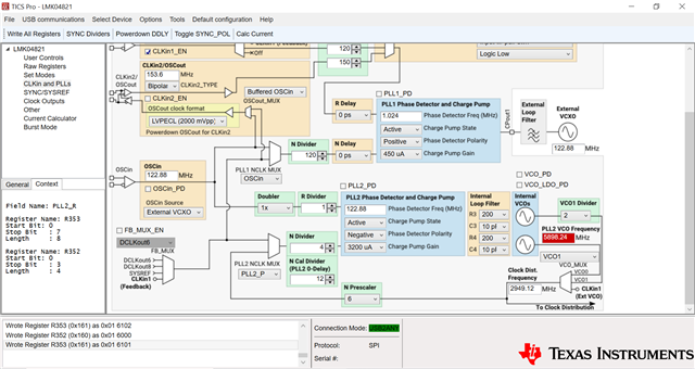
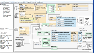
修改Doubler 和 Divider,可以在满足VCO输出频率范围的条件下锁相(Status_LD2 亮,但输出时钟频率不正确),配置如图三所示

图3:

  • Hi Well, 
    I am not following here?
    What is your config issue? I cannot tell from the images? 

    Also, can you post the text in English? 

    Regards, 

    Vicente 

  • Hi Vicente,

    1.I follow the LMK04821EVM User’s Guide quick start, set the default config as the picture 1, but the PLL2 Digital Lock Detect LED in top of the PCB did not light up. 

    2.Then I adjust the config, the VCO1 output frequency is 5898.24MHz(red color) as the picture 2, out of the datasheet shown, but the PLL2 Digital Lock Detect LED in top of the PCB light up.  The output clock locked successful.  

    3.Then I adjust the config again, as the picture 3. the Doubler of OSCin1 is set to *2. In this condition, the PLL2 Digital Lock Detect LED in top of the PCB light up too. But the output clock (from a spectrum analyzer ) did not lock at my set frequency.

    I am very confuse...

    Regards,

    Well

  • Hi Well, 
    To begin, can you tell me what your desired inputs and outputs are as well at attaching a .tcs file?

    I'll look into this and get back to you accordingly. 

    Regards, 

    Vicente 

  • Hi Vicente,

    The input clock is CLKin1 , 122.88MHz, -10dbm. Same as the User's guide.

    The test output clock is DCLKOUT0, 122.88MHz.

    And the power supply is 4.5V normal.

    Attached is the config of picture2.04821 dual loop.tcs

    Now I have two support need:

    1. Why the default config (CLKin1 122.88MHz, OSCin 122.88MHz)  with right VCO1 output f can't lock.

    2. Why the attached config with 5898.24MHz VCO1 output f can lock.

    Regards,

    Well Wang

  • Hi Well, 
    Sorry for delay, I didn't get opportunity to look into this today. I will look into this and hopefully have a response by tomorrow EOD. 

    Regards, 

    Vicente 

  • Hi Vicente,

    Hope have you reply soon.

    Regards,

    Well

  • Hi Well, `
    Can you confirm an ~122.88 MHz signal from VCXO? 

    Something seems off, VCO1 for LMK04821 is limited to the following frequency range: 

    Have you confirmed clk outputs when you the LED appears to indicate lock?

    Regards, 

    Vicente 

  • Hi Well,

    N-cal divider should be equal to N-divider. The default configuration has set this to 12, this is the reason why PLL did not lock. Change it to 6 then you should be able to get PLL2 locked.

  • Hi Vicente,

    I confirm the VCXO output is 122.88Mhz.

    And in the config I attached, when the LED appears to indicate lock, I confirmed the clk output is 122.88MHz by a spectrum analyzer.

    Regards,

    Well

  • Hi Noel,

    I change the N_Cal_Divider from 12 to 6,  and still don't locked, the config as the picture.

  • Hi Well,

    I don't why your board does not work. I don't have a LMK04821 EVM but I can duplicate your problem with a LMK04828 EVM. Can you confirm that your board is populated with a LMK04821 device?

  • Hi Noel,

    After check the device on the board, we confirm it is LMK04228, similar with LMK04828, so the problem I can understand now. Thank for you kindly remind and patience.

    Regards,

    Well