This thread has been locked.
If you have a related question, please click the "Ask a related question" button in the top right corner. The newly created question will be automatically linked to this question.
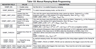
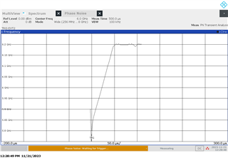
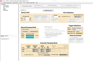
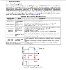
1- i wanted to generate a manual Ramp of 300 MHz from 5.6-5.9 GHz. in the least possible time. in tics pro software i didnt get the of setting ramp time in manual mode.. please help regarding this.
2- i have attached my ramping setting of tics pro file for generation of the ramp size mentioned above please verify wheather it is locking or not.. and improve if anything is wrong.
Hi There,
You are using manual ramp but the jump size is 300MHz, basically you are not doing frequency ramping but switching the frequency from 5600M to 5900MHz.
Anyway, if you want to use manual ramp, please check again below the requirements, your configuration has several conflicts with the requirements.
Hi,
Thanks for your response, I have modified TICS pro file based on your suggestion and I have attached. Please verify whether it is locking or not and also, I wanted to generate the ramp with least possible time. Please suggest any other setting is required to generate the ramp in least possible time. Thank you.
Hi There,
You should not use full assist in your configuration, you have a big 300MHz frequency jump, you need VCO calibration otherwise you don't have 300MHz frequency change.
use below configuration.
it takes approx. 100µs to change the frequency.
Hi Noel,
Thanks for your response and suggestion. I have some design requirement which I have plotted please refer this figure.
In this figure I have following points.
1) The start frequency 5600MHz and stop frequency 5900MHz, a band of 300MHZ.
2) In this band signal generation, I wanted minimum step size (how minimum step size (MHZ) can we use) and minimum time required for the total generation.
3) If VCO calibration is required then it can use minimum time for calibration (I think in full assist provide minimum calibration time, that is the reason I used full assist in previous design)
Please provide details regarding this waveform generation. If possible, please provide .tcs configuration file.
Hi Abhishek,
Do you want to sweep the frequency with the ramp engine or you want to do it manually?
The difference are:
With the ramp engine, you setup the start and stop frequency and the desired ramp time, the ramp engine will sweep the frequency to you. Please refer to the datasheet section 8.1.7 for the details. You also need to be clear on if you need linear ramp or not. If the ramp range is big, there will be several VCO calibrations in the middle of the ramp, linear ramp is therefore not possible. Please also check the EVM user's guide section 3.2.2 and 3.2.3 for application examples.
With manual sweep, you keep programming the frequency registers (e.g. PLL N, NUM) to change the VCO frequency. In this case, you can use full assist to reduce the frequency switching time.
Hi Noel,
Thanks for your response, We want to sweep manually with following points.
1) The start frequency 5600MHz and stop frequency 5900MHz, a band of 300MHZ. with 10MHz step frequency. (RAMP0 = 10MHz) and (RAMP1 = 0)
2) Ok with VCO calibration in middle of ramp.
3) Frequency band is 300MHz, therefore linear ramp is not possible, we want staircase sweep with 10MHz steps.
I have attached TICs file with these specifications. Please verify this whether generating properly or not. If not, please suggest what modification we have to make in the TICs pro. If possible, please provide TICS pro file.
Thank You. 5.6-5.9ramp_manual.tcs
Hi Noel,
I have one more doubt, can we generate 100MHz ramp in 100 microsecond time with 100 steps with 1MHz step frequency size.
Thank you.
Abhishek,
The team is currently out for the Thanksgiving holiday. Please expect a response by Monday (PST) for any further queries.
Thanks,
Kadeem
Hi Noel,
Please response for above two questions,
Q1)
We want to sweep manually with following points.
1) The start frequency 5600MHz and stop frequency 5900MHz, a band of 300MHZ. with 10MHz step frequency. (RAMP0 = 10MHz) and (RAMP1 = 0)
2) Ok with VCO calibration in middle of ramp.
3) Frequency band is 300MHz, therefore linear ramp is not possible, we want staircase sweep with 10MHz steps.
I have attached TICs file with these specifications. Please verify this whether generating properly or not. If not, please suggest what modification we have to make in the TICs pro. If possible, please provide TICS pro file.
I have one more doubt, can we generate 100MHz ramp in 100 microsecond time with 100 steps with 1MHz step frequency size.
Thank you. 5.6-5.9ramp_manual_10MHz_staircase.tcs
Hi There,
You should remove full assist and then provide a 300kHz signal as RampCLK then you can complete 300MHz ramp in 100us.
Similarly, for a 100MHz ramp and 1MHz step size and 100us duration, RampCLK needs to be 1MHz.
Please note, in both cases above, the calibration times are ignored. If there are calibration during the ramp, total ramp time will be longer.
Hi Noel,
Thanks for your help. I have some doubts please clarify. Our LMX2527 EVM board arrived, and we are working on that.
1) Can you please tell us the ramp generation and rampCLK, and Bandwidth relationship. it is possible to provide more than 250KHz (in the data sheet rampCLK mention less than 250KHz). please clarify.
2) we are working manual ramp generation with VCO full assist (band 300MHz, (5600MHz-5900MHz)), we are able to see only one signal. please clarify this how to generate
do help me out as we want to understand more about LMX-2572.
thank you.
3) can you please provide manual ramping configuration for any frequency at 100MHZ band with 10MHz steps.
thank you
hi Noel,
we tried to generate the manual ramp with the Eval board.. and did the following steps-
1- we set the PLL start Freq. PLL was locked . set VCO caliberation @30 MHz.
2- we selected manual ramping mode and given the steps of 1 MHz. @ RAMP_0 and 0 at Ramp_1 as we were generating one ramp only.
3- we set forced o/p as mentioned in DAtasheet. set ramp trgA as rising RAmp CLK and given 200 khz Ramp clk at pin. also st 21khz at ramp_Dir.we also enabled RAMP_CLK & RAMP_DIR at pin option.
and at last Enabled the ramp after writing all register. frequeny jumped to other freq just once so failed to do ramping.
is tt possible to generate manual ramping using EVAL board do we need to keep writing some register that i am missing..
PLease help.
Hi Abishek,
Let me attempt this in lab. I am currently sick but should have an answer for you by the end of this week.
Regards,
Vicente
Hi Abishek,
I have successfully ramped from 5600 MHz to 5900 MHz with a step size of 10 MHz using manual ramping:
Taking into account all previous requirements such as LD_DLY = 0 , PLL_DENOM = 2^32 -1 , OUT_FORCE = 1 and etc.
I did the following:
1. Configure Ramp page as in image above
2. Ramp_manual = 1
3. Ramp_EN = 1
4. Now every time you toggle "clock ramp" button under Manual Ramping Mode section you will go up 10 MHz starting from 5600 MHz.
Regards,
Vicente
One more thing, set VCO limit high to 6000 MHz not 5900 MHz, otherwise you won't be able to ramp up to 5900 MHz it'll stop at 5800 MHz.
thanks Vicents it worked ..
but for understanding LMX i would request you to help with my couple of doubts..
1- for manual ramping we need to set Ramp_clk which we did not used in the above case still we generated the ramp.. how so.. Is there any internal clk.. ??
2- with the same setting when we tried to do Ramping for our 3rd band 1.1- 1.6 GHz Ramp it was failing to generate it..
it would be great if you could help to clear this doubt.
Hi Abishek,
1. What do you have connected to the RampClk pin? If there is a rising edge at this pin - this will trigger the ramping.
2. To begin with, a 1.1 - 1.6 GHz RFout requires the outputMUX to be set to "channel divider:" When you did the sweep from 5600 MHz to 5900 MHz the outputMUX was set to "VCO" which effectively bypasses the output divider and just outputs your VCO frequency.
A 1.6 GHz RFout uses a VCO frequency of 4.4 GHz
Now the 1.6 GHz RFout is derived from a VCO frequency of 6.4 GHz that has been divided down.
Given the VCO frequencies no longer reside in the same VCO core, a VCO calibration is required in between.
Regards,
Vicente