This thread has been locked.

If you have a related question, please click the "Ask a related question" button in the top right corner. The newly created question will be automatically linked to this question.

LMX2594EVM: Calibration and lock time

Part Number: LMX2594EVM
Other Parts Discussed in Thread: LMX2594, , USB2ANY

Hello,

I'm currently doing some measurement on LMX2594 and I'm trying to find out the calibration+lock time for No Assist Mode and Partial Assist Mode, lock time for Full Assist Mode.

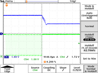
Since we don't have a signal source analyser here, I used a scope to measure directly the Vtune by trigger the CSB of the chip.

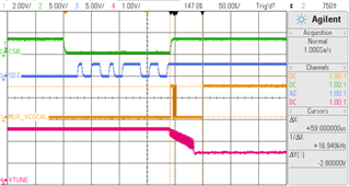
The measured calbration time for No Assist Mode and Partial Assist Mode are about 73us and 35-45us respectively, see below (the mesurement is triggered once the FCAL_EN=1):

Compared to the statement of the datasheet 50us and 35us (with 200MHz oscillator), my measurement is about 10us to 20us longer for these 2 modes, maybe i'ts OK since I use 100MHz oscillator here.

But for Full Assist Mode, I mesured 25us to 40us for lock time (calibration is skipped) which is too much longer compared to 5us:

Why the time is too much longer?

My thinking is that since the Vtune changed from its max or min value once the FCAL_EN=1 is written (not like in practice from one locked state (freq.1) to another locked state (freq.2) directly with small time gap), maybe it's normal to take longer. But the TICS Pro can write either only one register or all registers instead of just 2 or 3 registers to change to desired frequency...  

At this stage, I'm wondering if using Vtune is the right way to mesure the calibration+lock time... Do you have some suggestions for that?

Thanks in advances,

XL 

  • Hi,

    I'm using the similar method accroding to this past thread (by trigger CSB), however this donesn't solve my problem. As I described initially, I got little difference for Partial Assist and Full Assist....

    XL

  • Hi Xin, 
    Can you measure using MUXOUT and by having set it to LD and ensuring LD_DLY = 0 ? 

    Regards, 

    Vicente 

  • Here is a another detailed thread regarding lock time & measurement setup. 
    e2e.ti.com/.../lmx2594-lock-time-measurement-setup

    Regards, 

    Vicente 

  • Hi Vicente,

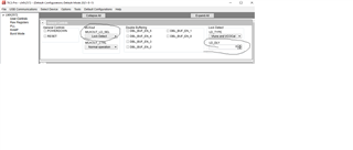
    I also used MUXOUT_LD_SEL=1 and LD_DLY=0, unfortunately I always didn't have the good calibration+lock time.

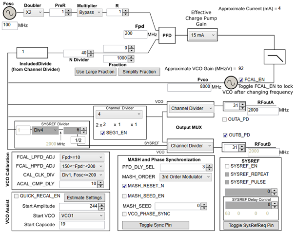
    The settings: 

    - OSC=100MHz (which is different from 200MHz where datasheet mentionned: state machine frequency is therefore 100MHz instead of 200MHz, so I expected 2 times slower for my results but I didn't)

    For Partial Assist: (LD_TYPE=0, tigger signal)

    The stable RF power at the output is achived even ~10us longer... (109us>97us > 35u*2us(datasheet)). I used the VCO calibration start settings above instead of calculated ones because I got about 150us in that case ! 

    For Full Assist: (for same freq. change) (LD_TYPE=1 or CSB, tigger signal)

    lock time (without calibration): 59us>50us>5*2us (datasheet)... far from expected lock time.

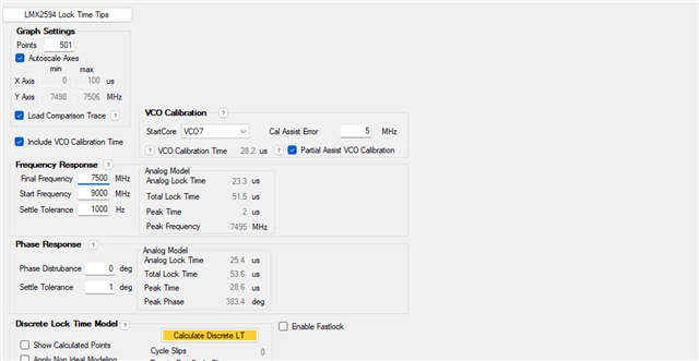
    However I suspect the loop filter design on the board LMX2594EVM may take 25us for analog lock for partial Assist on PLLatium Sim, could you comfirm it?

    However in PLLatium Sim there is no option for Full Assist.

    The calibration+lock time is quite important for our project and it is one of the critical factor for which we choose it or not. I appreciate your and your team's help.

    Sorry that the post marked as resolved by mistake, could you undo this pls?

    Thanks in advances,

    XL

  • Hi XL, 
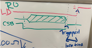
    To make sure I understand your plots and measurements, you're triggering using rising edge of CSB signal and measuring time until LD goes 'High' ? Note you measure lock time when programming R0 which triggers VCO calibration. 

    It seems you're measuring up till VTUNE (CH4) goes low? 

    Full assist is not an option given there isn't calibration going on, it only includes the analog lock time.  the user forces the devices to certain VCO cores & capcode. Refer to section 3.3 of this appnote for more info: https://www.ti.com/lit/an/snaa336a/snaa336a.pdf?ts=1704909627536&ref_url=https%253A%252F%252Fe2e.ti.com%252F

    Regards, 

    Vicente 

  • Hi Vincente,

    For partial assist, at the firt time I used CSB to trigger (1st post), then as you suggested I used MUXout (lock detect) to trigger (2nd post).

    I used lock detect signal from pin MUXout when MUXOUT_LD_SEL=1(lock detect) and LD_DLY=0. 

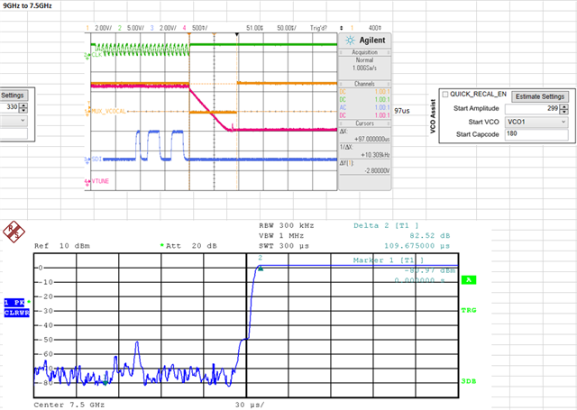
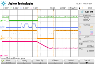
    Before I toggle R0 (SDI channel), to change from one frequency (locked) to the desired frequency (locked), the MUXout is always high as you can see in the screenshot below, then it goes low while CSB goes high once writing to R0 is done. After I changed the N values for desired frequency, before toggle R0, the PLL is unlocked; then toggle R0=1 to lock the PLL. Therefore the Vtune signal goes from 2.5V (unocked) to ~1.25V (locked) as seen in the screenshot below.

    So in my mesurement, whether I trigger CSB (high) or trigger MUXout_LD (low), I will get the same starting point of the time mesurement.The mesured time is from this triggered signal to high state of MUXout_LD (MUX_VCOCAL channel in the screenshot). So quite similar to your picture. But the calibration is about 104us which is too slow compared to datasheet. 

     9GHz to 7.5GHz

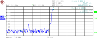
    I used the same triggering manner (trigger CSB (high) or trigger MUXout_LD (low)) and mesuring time until RFout is present 90%, the result is about 113us, then by substracting the calibration time 104us, I got 113-104=~10us lock time in this particular case.

     9GHz to 7.5GHz

    For Full Assist, I never used R0 since we force the VCO_SEL, VCO_CAPCODE and VCO_DACISET and there is no calibration at all. But in order to mesure the lock time on oscilloscope: 

    - change LD_TYPE to:

    - Firstly I lock the PLL at one frequency

    - then I changed N value for the desired frequency

    - then I forced these registers to 1

    - change VCO_DACISET, VCO_SEL and VCO_CAPCODE

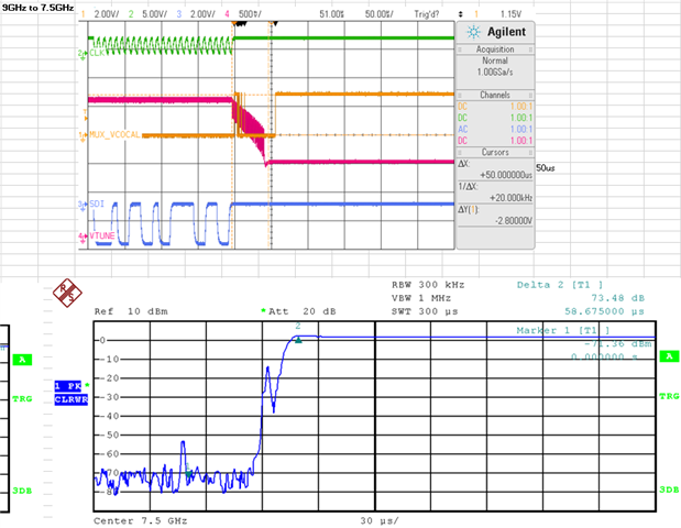
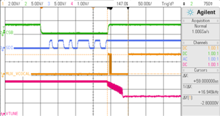
    - once the write of VCO_CAPCODE is done the PLL starts to lock and I mesured the time from starting point (trigged CSB) to MUXout_LD (high) as shown in the screenshot below. I got 59us which is too slow.

     9GHz to 7.5GHz

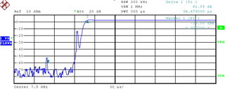
    and for zero span I got:

     9GHz to 7.5GHz

    Since there is no calibration, I estimate the lock time is about ~60 us from the 2 screenshots above (oscilloscope and zero span)...

    Hope that my explanation about my set-up and thoughts are clear for you.

    Thanks in advances for your response.

    XL

  • Hi XL, 
    Do you have a device capable of freq vs time measurements, I recommend customers lock time certain frequency and switch frequencies and measure the amount of time it took to reach your new target threshold frequency. It doesn't seem you're locked to a frequency originally?

    Vicente 

  • Hi XL, 
    I went into lab and using full assist to switch frequencies from 9GHz to 7.5GHz I achieved a ~20us lock time using TICSpro & USB2ANY. 
    USB2ANY SPI write speeds are very slow (125kHz) - if you used a much faster SPI write speed (like 70MHz) I'm sure you can reduce lock time even further.

    I locked to 9G first and then I changed PLL_N -> DAC -> VCO_SEL -> Capcode and I measured ~20us for lock time after programming Capcode. 

    What is your programming sequence step by step?

    Regards, 

    Vicente

  • Hi Vincente,

    I appreciate your response. We do not have an equipement to mesure Freq. vs Time. During the frequency changes from 9GHz to 7.5GHz, I followed exactly the same sequence as yours: 

    PLL_N -> DAC -> VCO_SEL -> Capcode

    At the moment when I changed PLL_N, the LMX2594 becomes unlocked and the Vtune goes up to about 2.5V which confirms "unlock". The PLL will re-lock after written Capcode (just like in your screenshot) and Vtune goes to about 1.25V (locked). Since TICSpro & USB2ANY only provides 125kHz, the chip is unlocked during a long period until it re-locks. 

    I got 59us for the lock time as shown below:

    And even 20us is 4 times slower than 5us...

    I don't understand why the SPI speed affects the lock time in Full Assist mode... For me the "complete frequency change" time between 2 lock states (9GHz to 7.5GHz) equals: SPI Programming Time + Lock Time. So speed up SPI time will speed up the "entire frequency change" time but not the lock time... 

    BR,

    Xin

  • Hi XL, 
    Please refer to section 3.1 of this appnote regarding why SPI speed matters: https://www.ti.com/lit/an/snaa336a/snaa336a.pdf?ts=1705011436322&ref_url=https%253A%252F%252Fwww.google.com%252F

    Can you provide a step by step procedure of what exactly your programming sequence is from start to finish? 

    Regards, 

    Vicente 

  • Full Assist Mode:

    Firstly I lock the chip to 9GHz with sequence/settings below:

    - DACISET_FORCE, VCO_SEL_FORCE and VCO_Capcode_FORCE=1

    - PLL_N -> DACISET=329 -> VCO_SEL=2 -> Capcode=103 : All of those read from rb_xxx registers before

    Then change the frequency to 7.5GHz:

    - PLL_N (chip starts to unlock)-> DACISET=291 -> VCO_SEL=1 -> Capcode=153 : All of those read from rb_xxx registers before

    The PLL will re-lock after writting Capcode at final step. I then mesure the time as you did.

    I read this acticle before

    and it seems it talks/compares the entire time: programming time+lock time which is what I just mentioned before. Except that the "unlock state" to "lock state" may affect lock time if programming speed is low, but didn't mention how much... 

    It compares the entire time "programming time+lock time" and we can observe the calibration+lock time is quite similaire from the figures abouve 3-1, 3-2 by excluding the programming time !

    Thanks;

  • Hi XL,

    I then mesure the time as you did.

    Just to confirm, you were able to measure the same time I did following the procedure I provided? 

    The reason SPI speed matters is to reduce the unlock period period when the VCO is drifting. The voltage of the capacitors in the charge pump don't get to change as much if the unlock period as reduced and thus don't require as much time to charge/discharge to return to their normal value. 

    Regards, 

    Vicente

  • Hi Vicente,

    No, I measured about 59us from 9GHz to 7.5GHz in full-assist. 104us for partial assist.

    BR,

    XL

  • Hi XL, 
    Would you have another EVM to test? Using identical procedure I was able to achieve an lock time of 20us and would expect you to get something close to that following the procedure I did where I go from 9G to 7.5G using full assist. 

    Regards, 

    Vicente 

  • Hi Vicente,

    I don't have another board to test.

    However I got ~20us lock time in full assis using a capcode which is smaller than what I get from readback...

    To be clear, when using the capcode from readback which is 153 for 7.5GHz (I confirmed this severals times), I got 59us from 9GHz to 7.5GHz; if I chosse capcode to be 147 instead of 153, I got about 20us lock time, the LMX2594 can still lock to 7.5GHz with this capcode setting...

    1. Is it normal when the capcode changes and PLL still lock to the desired freq. ?

    2. In worst cases, is it OK to do that (eg; using smaller capcode than that from readback) in practice ?

    Thanks.

    BR,

    XL 

  • Hi XL, 

    In regards to your follow up questions: 

    1. It is possible for the PLL to still lock if the capcode hasn't varied too much but now I have some follow up questions for you. 

    - Please measure and compare the VTUNE voltages with the different cap codes using full assist. I anticipate that for different capcode values you will have different VTUNE voltages. I would imagine for a smaller capcode value the VTUNE voltage will be larger. 

    2. It can be okay to do that but I do have another follow up question. What are you using to check that the device is actually locked? Are you using spectrum analyzer to confirm that the PLL got locked to 7.5GHz exact with both different capcodes? 

    Further recommendation, can you also try swapping the SPI series resistors from 12kOhm to 33Ohm? 

    Regards, 

    Vicente 

  • Hi Vicente,

    1. I mesured 1.8V for capcode 147 and 1.3V for capcode 153. 

    2. I checked the lock state by watching Vtune on scop, readback from rb_LD_VTUNE and verifying on frequency counter. LMX2594 locked for both capcode. And I checked it is locked for capcode from 145 to 165. What is the advantage for locking for a range of capcode?

    By the way, in full assist the rb_VCO_CAPCRTL is not correct... Is it normal?

    3. I could try to change the resistors for next steps. Is it a consideraion of time constant?

    BR,

    XL

  • Hi XL, 
    1. That is what I expected. The only issue with this is with the much larger VTUNE, you have reduced your tuning range for the VCO. The device will be less stable across temperature and is more prone to unlocking at higher/lower temperatures.

    What is the advantage for locking for a range of capcode

    2. Can you elaborate on this a bit more? I am not quite sure what you're asking here.

    I don't encounter any issues when using reading back for full assist capcode values. 

    3. That is correct! 

    Regards, 

    Vicente 

  • Hi Vicente,

    1. I am confused about the voltage=1.8V when capcode=147 in my case. For capcode=147 the locked frequency should be higher than 7.5GHz in normal case, thus the Vtune should lower than that for capcode=153 if still locked at 7.5GHz, isn't it ? Is Vtune proportional to frequency increase ?

    2. I checked this post

    https://e2e.ti.com/support/clock-timing-group/clock-and-timing/f/clock-timing-forum/1052172/lmx2594-interpolation-of-capctl-and-daciset-in-full-assist-mode

    it seems the threshold of Vtune is about 200mV, but why I still got lock detect indication when I have Vtune=1.8V?

    Thanks

    XL

  • Hi Xin,

    1. lower capcade means higher frequency. So the pll will try to lock it with a higher Vtune, as our charge pump has negative slope. 

    2. 1.8V is within the useable Vtune range, so the pll will lock.