This thread has been locked.

If you have a related question, please click the "Ask a related question" button in the top right corner. The newly created question will be automatically linked to this question.

LMX2572: Total delay range of SYSREF Delay circuit in Repeater mode

Part Number: LMX2572
Other Parts Discussed in Thread: ADC12DJ3200, LMX2594, LMX2595

Dear TI team,

we are using the LMX2572 PLL to clock some fast TI ADCs.

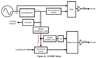
Two LMX2572 are located on two different PCBs that are provided with very low skew copies of input signals. These input signals are inherently alligned by a lower-speed PLL on each PCB first, such that SysrefReq always changes on the falling edge of OSCin, so that setup/hold times of the SysRefReq pin are guaranteed to be satisfied under all conditions.

The LMX2572 is in SYSCLOCK repeat mode, currently with a SYSREF Delay of 0 steps and are configured to synthesize three different configurable frequencies of either 2.0, 2.5, 3.2 when clocking an ADC12DJ3200 or 3.2, 4.0 or 5.0 GHz when clocking an ADC5200RF.

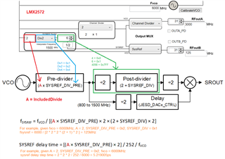
The following setup is used for the ADC12DJ3200 and feeding it with a 2.0 GHz clock, 

- f(OSCin) = 50 MHz
- f(SysrefReq) = f(OSCin) / 8 = 6.25 MHz

- Integer Mode (MASH Mode = 0)
- R_DIV = 1
- N_DIV = N' = N / 2 = 40
- Include_DIV = 2 (VCO_PHASE_SYNC_EN = '1')
- f(VCO) = 4000 MHz
- f(INTERPOLATOR) = 1000 MHz
- CH_DIV = 2
- OUTA_MUX = CH_DIV
- --> RFOutA = 2000 MHz

When applying the different delay values as described in the datasheet "Table 140. SYSREF Delay Step" I observed a (to me at least) weird behavior. With the setup utilizing a SYSREF_DIV_PRE = 2 the delay step is described in the data sheet being approx. 5 ps per step. I always wondered, why the LMX2572 has values depending on a divider, whilst the LMX2954 seemingly does have a constant delay step of 9ps ... but hey.

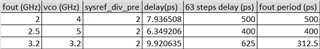
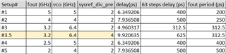
With steps of a fixed size (as the mentioned ~5ps) it would be expected, that the number of steps required to shift RefOutB (SYSREF) for a full period of RefOutA, would be different for these different periods of 312,5 ps, 400 ps or 500 ps respectively.

But when looking at RefOutA and RefOutB on a fast Scope, triggering on RefOutB, the observations with the three different setups 3.2/2.5/2.0 GHz are: applying different delays, the delay shifts by one RefOutA period (360°)  with ~62 steps applied, in all the three RefOutA speeds.

How could that be, if the step size is the same for all the three different frequencies ?

Best regards

Bjoern

  • Hi Bjoern, 
    I am a bit confused help me understand here. 
    What you're saying is that you're not seeing the appropriate SYSREF step size delay? 

    But I agree, the amount of steps needed to shift SYSREF for a full period of RFoutA for 2GHz, 2.5 GHz & 3.2 GHz should be different. So you're saying it takes the same amount of steps for all three output frequencies (62 steps)? 

    Regards, 

    Vicente 

  • Hi Vicente,

    yes,

    I set my scope to trigger on RFOutB (Sysref) and observe the phase shift of RefOutA. With each ShiftStep therefore the clock "shifts" relative to the Triggerpoint, whilst of course in reality the RefOutB shifts with respect to the clock.

    My observation is, that

    - a) for three of my five LMX setups I am seeing a 360° shift (degrees referred to RefOutA clock) with the mentioned 62steps. These setups include a channel divider of " and a R-divider of 2. One of such setup is mentioned above.

    - b) for two of my five setups I am seeing a 360° shift with approximately half the number of steps. In my measurements with 33 steps. The setups for these tests use an R-divider of 1 and also use direct VCO output (so a channel divider of 1).

    Since the delay circuit at least with the LMX2572 is documented to be somwehat depending on some divider, it could be assumed that this delay is indeed a clocked one, and not some analog delay. But the datasheet implies that no matter what these steps do have a somewhat fixed length and are not in degrees of F(VCO) or similar. 

    So clarification is needed and welcome. 

    Best regards

    Bjoern

  • Hi Bjoern,

    First off, sysref delay depends on SYSREF_DIV_PRE, this is true for LMX2572 and LMX2594.

    The amount of sysref delay is also VCO frequency dependent. 

    If my calculation is correct, we should get below delay time. 63 steps because each JESD_DACx_CTRL counter is 63.

    I need to confirm my calculation with the designer before I send you the formula. Stay tuned.

  • Hi Noel,

    thanks for investigating and keeping me posted.

    SYSREF_DIV_PRE is always set to 2 in out setups, so that we have assumed delay steps of ~5ps, as mentioned in the LMX2572 data sheet.

    We are using these five different setups:

    According to my measurements the first two setups (with CH_DIV and R-DIV active) yield to 360 shift with ~33 steps and the other three setups do get a full 360° shift with the aforementioned 62 steps.

    Dean once posted quite a detailed specification for the SYSREF delay (LMX2594: SYSREF delay circuit - Clock & timing forum - Clock & timing - TI E2E support forums) and since this does not mention a specific VCO frequency, (unless I missed that part) I was more expecting this to be VCO independent. This would also match the "static/fixed 9ps" step size mentioned in the LMX2594 data sheet. This this size is not only SYSREF_DIV_PRE but also f(VCO) dependent is quite a surprise to me.

    Best regards

    Bjoern

  • Hi Bjoern,

    Thanks for the measurement, it helps as I don't have a very good scope to do ps measurement at the moment. 

    Your data matches exactly as my calculation, I have more confidence that my calculation is correct. 

    I do not see the configuration in Dean's report, but for sure the delay is VCO frequency dependent as shown in below block diagram.

  • Hi Noel,

    thanks for sharing your calculated values !

    I would like to point out, that it indeed matches your calculations, but from my point of view it only does so in the cases #3, #4 and #5.

    In the cases #1 and #2, I was not able to measure the calculated 63 steps but half of it. (~33 steps) So in these cases the step resolution seems to be halved, which is quite a difference.

    If there is a way to calculate that variation from f(VCO), why is that not mentioned in the data sheet or sheets, since I suspect that this is quite similar with LMX2594 and LMX2595 as well, or isn't it  ?

    From the current LMX2594/LMX2595 data sheet I have assumed that this is a completely fixed value with ~9ps step size, since in contrast to the LMX2572 in the 94/95  data sheets there is no documented delay/stepsize variation from even SYSREV_DIV_PRE.

    That there is "somewhat" a relation to "a clock" is indeed indicated by the block diagram, but as far as I understood it - and please correct me if I am wrong - the re-clocking and maybe also the delay part does not only receive one single frequence f(interpolation), but also at least f(RFoutA) and I suspect also f(OSCin) for enabling Category 2 sync. 

    Best regards

    Bjoern

  • Bjoern,

    In case #1 and #2, a fout clock period is 200ps and 250ps, respectively. 63 steps of the delay counter can make 400ps and 500ps delay, which is equal to 720 degree. In other words, we only need 31.5 steps (=63/2) to make a 360 degree delay.

    The same sync and sysref block diagram applies to both LMX2572 and LMX2594.

    After getting confirmation from the design team, we will update the datasheet. 

  • Hi Noel,

    oh yes of course #1 and #2 could cover two periods and hence ~32 steps are enough ... doh. 

    So I assume that this f(VCO) dependent stepsize is also valid for the bigger brothers of the LMX2572, like e.g. the LMX2594 and LMX2595 and should be noted in their respective datasheets as well IMHO, if it happens to be that the same principles apply.

    And while you're at it, you could also maybe take a look here in an older post of mine from a few years back, where there was also a discrepancy between the data sheet, TICSpro: https://e2e.ti.com/support/clock-timing-group/clock-and-timing/f/clock-timing-forum/962680/webench-tools-lmx2572-tics-pro-bug-at-lmx2572-wrong-post-sr-divider-input-frequency-range/3556814

    To my best knowledge, since there has been no new revision of the LMX2572 datasheet, so this is yet unfixed and the incorrect "Post-SR divider" range of 400 to 2300 MHz is still mentioned.

    Best regards

    Bjoern

  • Hi Bjoern,

    We did not forget to update the datasheet, but the process to make the change is not straight forward, my strategy is fix all the errors in one time rather than keep updating the datasheet from time to time. I have gathered sufficient changes and I will request for a datasheet update in this year. 

    In LMX2572 product folder, click the bell and register, you will be notified when a new datasheet is released.

  • Forgot to attach the sysref diagram and equations.

    Below shown the block diagram and equations, same for both LMX2572 and LMX2594/95.