LMX2582: Frequency offset

Part Number: LMX2582

Hi team,

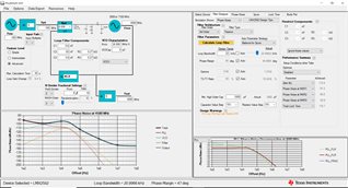
Whenever i am configuring frequency from the Tics pro.I Observed the output which is having more 1 MHz offset.

Can you guide me how to adjust that offset in LMX2582 chipset.

Please find the .tcs file Tics pro files.tcsattached

  • Please find the loop filter values for 4830MHz Frequency output.

    Can you please suggest correct loop filter values since LMX not locked Properly

  • Hi Manasa,

    This problem is likely due to the reference clock and the test equipment are not synchronous. 

    What reference clock source are you using? If it is a signal generator, did you connect the 10MHz output (at the rear of the equipment) to the test equipment's 10MHz input?

    Your loop filter design is fine.

  • Hi Noel 

    we are using  CWX813-100.0M clock as reference frequency.

  • Hi Noel 

    Is there any changes required in the crystal components

    Please find the below schematic

  • Hi Manasa,

    it is a crystal oscillator, we cannot change its frequency with external components. 

    This oscillator has 25ppm frequency tolerance, so the synthesizer output will also has 25ppm tolerance. That is, ±120.75kHz. Since you are seeing 1MHz offset, seems to me your test equipment may need calibration. 

    Please also note, OSCin requires AC-couple. 

  • Hi Noel,

    Small observation today 

    Crystal output frequency 100MHz and power level +2 dBm with voltage swing VPP 0.93mV gave as a reference clock to LMX 

    We observed LMX is not locking properly in the span of 10KHz .Peak is moving continuously is this because of loop filter? 

  • It would be helpful if you share tics pro file based on this loop bandwidth settings

  • Hi Manasa,

    Your loop filter and TICS configuration are fine. 

    2dBm seems a bit low for a CMOS oscillator, probably due to the 68Ω shunt resistor.

    Try below modification and check again the voltage swing at OSCinP. 

  • Hi Noel,

    It would be helpful if we discuss over Mail/Call further  to have a better understanding of the issue. 

  • Hi Manasa,

    Let's stay on this platform first.

    Since you are using TICS Pro to program your board, we can eliminate it is a software issue, we can focus on hardware.

    If you configure MUXout as lock detect output, is MUXout output high after programming? If MUXout is high, then the PLL is locked. The drift you saw would be due to other reason. Reference clock is one of the suspects. Could you provide a screenshot or a short video showing how does the drift look like?

    If MUXout is low, the PLL is not locked. in this case, you should get a very different frequency but not something within a 10kHz span window. 

  • Hi Noel,

    One more observation from my side

    When we gave reference frequency 100MHz from signal generator PLL locked properly .So it was clear there is no issue in the PLL.

    When we checked output of the crystal we observed 8KHz offset in the crystal output 

    Once we connected crystal output to LMX the output of LMX not Locking properly when we reduce the span we observed around 22KHz offset in LMX output

    I will attach small video for your reference. We are suspecting the components between LMX & crystal.

    Please suggest your thoughts as  well

  • Hi Manasa,

    Did you try the modification I suggested earlier?

  • Hi Noel,

    Yes, I tried modifications based on your feedback .

    one more observation from my side is crystal ic ground not soldered properly. After proper soldering also the offset from the LMX is 8KHz and peak is slowly moving towards center.

    Please find the below image the components between LMX and crystal and small video for your reference

  • Hi Manasa,

    Please try again with AC-couple.

  • Hi Noel,

    Sorry for the confusion final observation from our side is

    we observed 0.2KHz offset from the 100MHz crystal. When we are feeding to PLL it is not correcting the offset and the output of PLL we observed 8KHz offset.

    What will the acceptable offset from the clock to LMX2582.

  • HI Manasa,

    When fosc = 100Mhz and output = 4500MHz, the ratio is 1:45. If fosc is offset by 0.2kHz, then the output will offset by 0.2k x 45 = 9kHz. PLL will not correct the offset from fosc, as fosc is the reference to the PLL, the PLL will following the offset from fosc.

  • Hi Noel

    I had like to confirm whether it's preferable for an OCXO to have a CMOS output or a Sinewave output as a reference clock to LMX2582.Since we are planning to get a precise output like less than 100Hz variation of signal from LMX output.

  • Hi Manasa,

    Sinewave is fine if OCXO frequency is 100MHz.