This thread has been locked.

If you have a related question, please click the "Ask a related question" button in the top right corner. The newly created question will be automatically linked to this question.

LMX2582: Loop Filter

Part Number: LMX2582

Hi Team,

I hope this message finds you all well. My name is Manasa, and I am currently working on a project related to Up & Down converters. I've come across a challenge regarding LMX2582 Loop filter, and I'm seeking insights or guidance from the TI Team

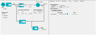
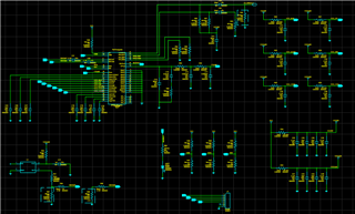
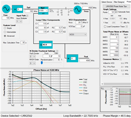
Below attached image related to loop filter. Can you suggest suitable schematic and loop filter Values for Output Frequency (4580MHz)

.

  • Hi Manasa,

    What is your target performance specification to the synthesizer? For example, phase noise requirement, is it a fixed frequency application or you need to sweep the frequency, etc.

  • Hi Noel Fung,

    Thank you for replaying me

    Its a fixed frequency application .Fixed frequency  we are choosing  in between range (4.5 to 5.5GHz)

    Input Frequency : 100MHz

    Phase noise : @10KHz <-80dBc/Hz,@100KHz <-100dBc/Hz

    Can you check my schematic and confirm everything is proper for this application 

  • Hi Manasa,

    Phase noise is not an issue, LMX2582 can meet this requirement with margins. If your frequency requires fractional PLL, maybe you should consider to use 3rd order filter.

    Your picture is hard to read, could you provide a higher resolution picture?

  • We are planning to design LMX2582 with below Specification

    Ref Frequency :100MHz using a CWX813-CWX823

    Supply Voltage :3.3V

    Output Frequency : Fixed Frequency (Ranges in between 4.5 to 5.5GHz)

    RF Output : RFOUT AM - Single ended output

                       RFOUTAP - Terminated

                       RFOUTBP - Terminated

                      RFOUTBM - Terminated

    OSC in : OSCinp - 100MHz Ref in single ended

                  OSCinm - Terminated

    Can review the schematics and help us to choose best Loop Filter Values and as well as any changes in the schematics required

    CSB,SCK,SDI,MUX out pins we are planning to connect to a micro controller (STM32F070F6P6TR).Is it okay to use this micro controller to control the micro controller.

    8053.LMX2582.pdf

  • Hi Manasa,

    Y1 should be AC-couple to R31, otherwise there will be too much current flow via R57.

    R55 could be zero ohm. R57, between 50Ω to 100Ω, it is used to adjust the voltage swing going to OSCinP.

    We can combine R56 and R58 to a single resistor that match the value of R57. Or we can make it zero ohm to GND. I don't see notice difference with or without this resistor.

    R64 and R65 are not needed, just leave the pins floating.

    You can try below configuration.

    We use standard SPI interface, any MCU should work.

  • Hi Noel Fung,

    Thank you for helping us .I have made some changes in the schematic please review the schematics if anything missing please help us.

    LMX2582_Updated.pdf

    In this schematics LV4 indicates no component. And red color boxes indicate changes done or expected changes to be made.

    And some queries from my side 

    1.In this schematics C11 capacitor highlighted near to loop filter is it required ?

    2.R63,R64,R65  terminate with 50ohm resistor creates any issue if I am planning to use single ended output from RF Out AP ?

    3.To increase the power level from the LMX we need to use inductor pull up as per datasheet what is the best value to get better from LMX2582.

    4.As per loop filter calculation @10KHz -94.8dBc/Hz .Is it any way to increase it to less than -100dBc/Hz

  • Hi Manasa,

    R22 is 0ohm, so indeed you are using 3rd order filter. C11//C64 is the third pole capacitor. It is your decision to split this capacitor or not. Anyway, make sure the layout has the last pole's capacitor sitting next to the Vtune pin. 

    You do not use RFoutB, you do not need R64, R65.

    R63 is needed.

    Datasheet Figure 6-13 shown the test data with inductor pull-up at 5.4GHz. 18nH seems to be a good starting point to you.

    You can increase the loop bandwidth further to reduce 10kHz phase noise.

  • Hi Noel,

    Thank you for sharing a valuable feedback. Once layout done, I will share layout file for your review

  • Hi Noel,

    Hope your doing well

    I wanted to share layout file for Review purpose. It would be helpful if you share your email id to contact further

  • Hi Manasa, 
    Noel is currently out of office. 
    You can share your layout file with me: v-floresprado@ti.com

    Regards, 

    Vicente