This thread has been locked.

If you have a related question, please click the "Ask a related question" button in the top right corner. The newly created question will be automatically linked to this question.

LMK04828: unexpected doubled steps with digital delay

Part Number: LMK04828

Tool/software:

Hi all, 

In our application, we need to dynamically control the phase of a clock respect to the relative  data. 
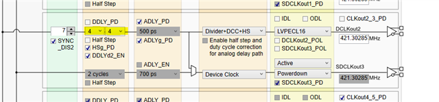
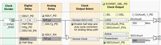
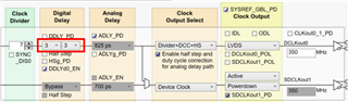
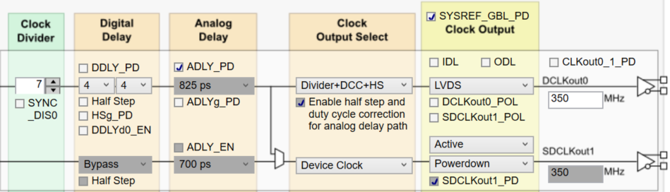
For this application we are trying to use the LMK04828 (using the relative demo board LMK04828EVM) and we followed the datasheet configuration for a 350MHz input and output clock with zero delay mode.

Outputs are sync with the input.
We  are correctly able to apply an analog delay but the problem is with the digital delay:

We are not able to control in a "stable" way the advance or the delay of the clock with digital delay.


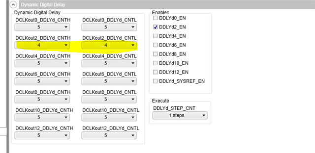
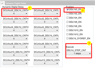
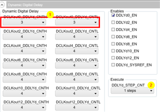
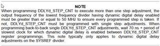
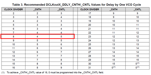
The clock use an internal divider of 7 and so following the procedure described at section "9.3.3.2 Dynamic Digital Delay" and we set values for DCLKoutX_DDLY_CNTH/_CNTL to have 1 single step of delay :

TO GO FORWARD :  _CNTH = 4 and _CNTL = 4
TO GO BACKWARD: _CNTL = 3 and _CNTL = 3

and after we applied a DDLYd_STEP_CNT = 1,  expecting that this provide each time 1 simple step of the clock phase or forward or backward (depending on the previous DDLY_CNTs)

Unluckily doing an automatic test that moves the clock 3 steps forward and 3 backwards we notice that sometimes there is an unexpected shift with one of the step that is DOUBLED, resulting in a total of 4 steps in advance (or  in delay) instead than the expected 3.

For us is mandatory to have a stable and predictable phase delay.

Is there something wrong in the configuration? 
is there something else we could try or is this an expected behavior ?

thanks in advance.


  • Alberto,

    I apologize for the delay.  I have tested this in the lab and I am able to replicate your issue in the lab.  

    I believe the fix is to ensure that DCLKoutX_DDLYd_CNTH/L and DCLKoutX_DDLY_CNTH/L are set to the same value.  

    Regards,

    Will

  • Hi Will

    we tried that but without success

    the "forward" with all "4" still works 

    the "backwards" with all "3" still makes shifts after a few times

    any other suggestion?

  • Alberto,

    I will debug in the lab tomorrow to see if I can find anything else.  

    Regards,

    Will

  • Alberto, 

    Could you share the register writes that are testing this functionality, so that I can test your config. If you can share a TICSPRO .tcs file as well that would be very helpful. 

    Regards,

    Will

  • Hi Will, 

    here is the tcs file content

    LMK04828_PD87_5_feedback_CK6_v05.tcs

    Monitored port is port CLKout0

    then the manual procedure is:

    To apply a delay "forward" we set 

    DDLY_PD H/L to 4

    DDLKout0_DDLYdCNTH/L to 4, enable DDLYd0_EN

    and Execute 1 step

    to apply a delay "backward" we set 

    DDLY_PD H/L to 3

    DDLKout0_DDLYdCNTH/L to 3

    and Execute 1 step

    In our test, we don't use a manual procedure, but we control the chip from our embedded controller:

    We set the clock in the middle of the clock/data eye

    we define the number of steps backward and forward that we want to have (steps_val): 
    * NOTE: the movement is always of 1 step, but repeated "steps_val"  times
    * NOTE: after a cycle, the clock /data relation should come back to the same position

    we define the number of cycles

    we run the test

    when monitoring via the oscilloscope we can see that once in a while on the "backward" direction, one step is skipped

    this is confirmed because at the end of a few cycles, the clock/data relationship has changed compared to the beginning of the test

    the same outcome could be monitored comparing the CLK0 under test to another cloch where delay is not applied

    here is a simplified snapshot of the code that does
    (steps_val is the number of steps )

    while do_loop!= False :
    sleep(0.5)

    i = 0
    ##FORWARD
    write_CLK_DIST(0x0102,0x44,1)
    write_CLK_DIST(0x0101,0x44,1)
    while i != steps_val :
    sleep(0.5)
    write_CLK_DIST(0x0142,0x01,1)
    i = i+1
    sleep(0.5)

    i=0
    ##BACKWARD
    write_CLK_DIST(0x0102,0x33,1)
    write_CLK_DIST(0x0101,0x33,1)
    while i != steps_val :

    sleep(0.5)
    write_CLK_DIST(0x0142,0x01,1)
    i = i+1

    sleep(0.5)

    please let me know if this helps

  • Another comment Will: 

    We could extract the command to send for DDL_PD setting using the GUI, but this register (0x0102 for CLKout0) seems to not exist in datasheet 

    thanks

  • Alberto,

    Thank you for the thorough information.  I am continuing to investigate this.

    Regards,

    Will 

  • Alberto,

    I've been looped in to offer my thoughts. I'm coming back from extended out of office time so it will take me a bit of time to get the full context.

    For now, I recall a note from the LMK04828-EP datasheet that I never got the chance to port back into the LMK04828 datasheet. I'm not sure if it's applicable to your situation, given that your frequencies seem high enough to avoid this issue, and given that the description of the consequences (omitted delay step) seem at odds with your problem description (extra delay step). But I'm posting it just in case.

    I'll keep thinking on this and offer more thoughts on Monday US time.

  • Hi Derek, thanks for your support

    I agree this doesnt seem to apply: 

    all our clocks are 350M

    we always do 1 step adjustment (repeated N times, bu alwys 1 step at a time)

    given the SW loop, the delay between adjustments is > than (70ns + 2.8n period) 

    feel free to let us know if you have further considerations

    thanks 

  • Alberto,

    We are still looking into this thread and will get back to you with an update once we have more information.

    Best,

    Andrea

  • To my knowledge, I've never seen anyone request a step backward before. It may not have been validated.

    I'm temporarily away from the lab so I can't test this myself, but I'm passing it along to the rest of the team to try. In the mean time, you're also welcome to test and check the results, if your setup allows:

    • Theory 1: Interaction between DCC+HS and dynamic delay
      • With DCC+HS on, half of the clock edges are aligned to the falling edge of the VCO instead of the rising edge. This may create a race condition for counting VCO cycles, or it may duplicate counting in an unexpected way.
      • To test whether DCC+HS impacts the dynamic delay function, you could set DCLKoutX_MUX to divider-only and repeat the tests.
      • You could also try programming CNTH to 4 and CNTL to 2 - maybe DCC+HS requires CNTH to round up on odd divides?
    • Theory 2: Something is wonky with odd divides
      • No detailed mechanism in mind, just maybe odd divides are weird
      • We could test alternate frequencies with even divides (with or without DCC+HS, for even divides it shouldn't make a difference) and see if the issue is ever observed.
    • Theory 3: Something is wonky with divides < 8
      • In general, high-speed dividers that are both programmable and that support values beyond just power-of-2 steps take a lot of design overhead to implement correctly. It's possible that there are issues with dynamic digital delay that were never observed because the values at which they are observed were too high-frequency for the measurement equipment used in the original dynamic delay validation.
      • Once again, we could test alternate frequencies with high/low divide values and see if the issue is ever observed.

    I think you should be able to try at least Theory 1, and maybe some easy cases for theory 2 or theory 3 (divide-by-8, divide-by-9). We can also try all of this on our end, provided I can get someone to set it up in the lab tomorrow.

  • Hi Derek, 

    I'm also temporarily away from lab for a couple of weeks, so I'll see if my colleagues have the possibility to test some of these options

    BTW, changing divider may not  be possible: given the fact we need to generate a 350M clock, the only frequency that fits in the two VCO ranges is in fact the current one with divider by 7 (2450)

    350 multiplied   x7 = 2450, x8=2800, x9=3150

    • VCO0: 2370-2630
    • VCO1: 2920-3080

    I'll keep you posted if we manage to perform some test

  • Great, we'll try to perform the same tests on our end.

    I understand that your application is probably stuck with the divider value you've chosen - my aim was purely to get alternate data points disregarding the final output frequency, i.e. debug the dividers by changing parameters and observing resulting behaviors. In any case, we have your .tcs file, so it should be straightforward for us to perform these tests ourselves.

  • Alberto,

    Just wanted to provide you an update. I am still tryin to replicate your issue and try our potential fixes.  I will update you when I find something new.

    Regards,

    Will

  • Hi Will, 

    just for information, we tested yesterday a configuration with even divider as suggested by Derek: 

    Divider 8 

    TO GO FORWARD :  _CNTH = 4 and _CNTL = 5
    TO GO BACKWARD: _CNTL = 3 and _CNTL = 4

    results is still the same : errors on "backward" direction

  • William Sorry, I correction to my previous mssage:

    TO GO FORWARD :  _CNTH = 4 and _CNTL = 5
    TO GO BACKWARD: _CNTL = 3 and _CNTL = 4

    results is still the same : errors on "backward" direction

    results is that we sometimes observe "double steps" even if we ask for 1 step and this happens both in backward and forward direction 

  • Alberto,

    Thank you for the information.  I have finally been able to reproduce your issue after creating a script similar to the one you have shown.  I will try Derek's suggestions and see if there is any way to find a root cause of these glitches.

    Regards,

    Will

  • Alberto,

    Just wanted to provide an update.  I have been unable to reliably reproduce the glitch over several thousands of delay steps.  How often are you able to replicate it?  

    Just know we are continuing to try to find the root cause, any additional information would be appreciated.

    Regards,

    Will

  • Let me quickly clarify - we reproduced the reported issues a few days ago, but upon revisiting the test setup for more extensive evaluation we have been unable to reproduce the issues again. There may be setup steps that must/mustn't be executed which result in dynamic delay working as expected in some cases, but failing occasionally in others. We know something is definitely going on, because we have seen it - but it's not clear what changed from a week ago.

    We have the pseudocode you used to evaluate the dynamic delay function, and your tcs file with the initial register settings. Were there any other steps taken during testing? Did you synchronize the dividers, for example? I see that your initial post indicates output are synced with input, I'm not sure if this just means the PLL is locked or if this means a sync procedure was performed first, e.g. the procedure from datasheet section 9.3.3.1.

  • Hi Derek,

    The test is really minimal, with no additional procedures beyond power-up, loading the TCS file, visually checking that the reference clock and the clock we intend to monitor are locked, and then running the test (using an external SPI controller with a Python script).

    Sometimes, to have an easier visual reference point at the start, we have applied manual shifts with the TI tool to align the clock edges before starting the test (the expectation was that by moving X steps forward and X steps backward, it would return to the same point). In any case, whether we started aligned or not, the problem always occurs.

    To make the investigation easier, I have created a HEX file that replicates our test by running the forward/backwards sequence about 50 times, which can be launched directly from TI's TICs Pro tool and the same programmer.

    The procedure is reduced to the minimum:

    1. Power up
    2. Load configuration with the TCS file
    3. Visually check that the clocks are locked on the oscilloscope
    4. Load the HEX file from TICs Pro using: file -> import hex register file

    The problem is always evident, and often it only takes two or three repetitions forward/backward to see that the sequence has gone out of the expected window.


    P.S.
    In the configuration file, in addition to writing the counters for the divider and the trigger to apply the delay, I included some dummy writes to the "R142 0x014200" register, which only serve to slow down the shifts so that they are easier to see on the oscilloscope.


    50xsingle_seq_test.rar

  • Alberto,

    Thank you.  I am now able to irrepealably observe the delay glitches within 50 or so delay adjustments.  I will update you next week after further testing. Thank you for your patience.

    Regards,

    Will

  • Alberto,

    Thank you for your patience.  I think I have found the root cause of your issue. 

    It seems that the LMK04828 is only capable of doing dynamic digital delay steps in one direction before doing a SYNC event to change directions.  As stated in the LMK04828-EP datasheet: (which seems to have not been updated in the LMK04828 datasheet, but will now be)

    This means that upon SYNCing the dividers at the start and then toggling the DDLYd_STEP_CNT to step forward, the DDLYd_CNTH/CNTL& DDLYd_CNTH/CNTL cannot be changed without a SYNC event.  Derek encountered a similar bug a few years ago here - "During the dynamic digital delay, the values for d_CNTH/d_CNTL are substituted in place of the divider behavior, but the static digital delay counters are still running again in the background (because dynamic digital delay is effectively a SYNC event). So it's possible when the static/dynamic delay values are different that the clock could switch into a divider that is still awaiting delay completion."

    Given that you are seeing correct forward steps and only seeing glitches upon trying to move backwards after, this theory seems to make sense.

    In order to get around this limitation of only being able to step forward, you can create an effective step backwards by stepping forward all the other relative clock outputs using the enables.  

    Let me know if you have any other questions!

    Regards,

    Will

  • Hi William, 

    unfortunately this will not be possible in our application as we are looking for an "absolute" input to output delay and not a relative delay from one to the other outputs:

    That's why we work in ZDB mode in order, clocking a data that is synchronous to the input clock

    Delaying all other signals will have an impact on all the other ck/data synchronization and won't have the desired effect on the specific clock 

    I'm really sorry but we will need to change to a different solution as this device won't be able to support the application and we have already delayed too much the launch of the next prototypes spin

    thanks for the support, we appreciated it

    Alberto