This thread has been locked.

If you have a related question, please click the "Ask a related question" button in the top right corner. The newly created question will be automatically linked to this question.

LMK04832: Whether does SYNC need to be synchronized by reference clock to LMK04832 when I want to sync Multi-chip of LMK04832?

Part Number: LMK04832
Other Parts Discussed in Thread: LMK04828, LMK04616

Tool/software:

Hi, 

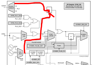
I have a question about how to provide sync pulse to  multi-chip of LMK04832: 

Need SYNC pulse to be synchronized to reference clock to LMK04832? Could below two schemes get the same synchronization accuracy?

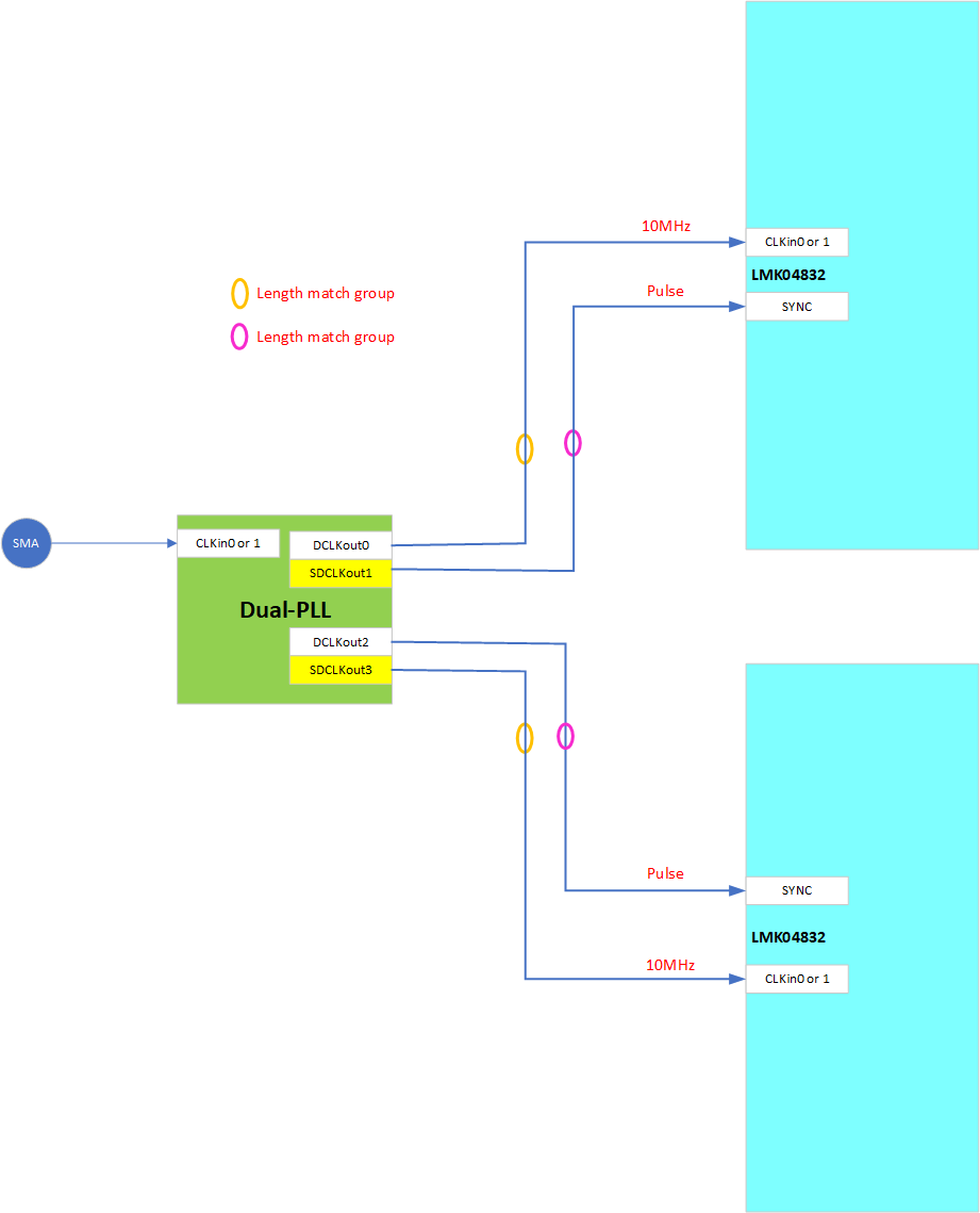
As below figure.1 shown, reference clock and Sync pulse all come from another dual-PLL such as LMK04828 or LMK04832. Under this case, Sync pulse from SDCLKout of dua-PLL is synchronous to DCLKout which is  reference clock to CLKin of next LMK04832
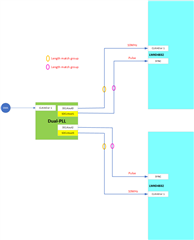
Figure.1 

As below figure.2 shown, sync pulse come from MCU or CPU through Buffer fanout. This sync pulse are asynchronous to reference clock of next LMK04832 totally.
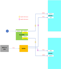
Figure.2

Thanks in advance!

Best regards!

Jason

  • Jason,

    There should be no difference in using either method. Choose whatever makes more sense to your system.

    Best,

    Andrea

  • Hi, Andrea:

    I have read application report named "JESD204B Multi-Device Synchronization Using LMK0461x", and it is why I ask the question in this thread. In this report, Configuration 5 is similar to Configuration 3 with the difference being that the SYNC/SYSREF_REQ is not coming from the Device-1 synchronous to the clock, but is asynchronously applied to the two slave devices. If SYSREF is used in Pulsed mode from the slave devices, then from the SYSREF_REQ edge to the rising edge of the SYSREF at the output of the two salve deices might differ by one SYSREF cycle. The LMK04832 is similar Dual-PLL chip with LMK04616, so I think LMK04832 also have the same situation. But, in my application, I must align all SYSREF output from the the two LMK04832 anytime.

    Figure.1: Configuration 3

    Figure.2: Configuration 5

    Thanks a lot!

    Best regards!

    Jason

  • Jason,

    I believe what you want to make sure of is that the outputs of devices 2 and 3 in the picture are aligned. To ensure alignment, the importance is that the pulse signal going to the SYNC pin arrives at the same time on both devices so both devices can SYNC the dividers with the same pulse and therefore result in aligned outputs. 

    Based on the article you referenced this can either be done by using configuration 3 and setting SYSREF to be continuous or using configuration 5. What the article explains is to not use pulsed SYSREF when using configuration 3 to ensure complete alignment on all SYSREF outputs. In other words, I would recommend for you to use Figure 2 from your original post.

    Best,

    Andrea

  • Hi, Andrea:

    Thank for your response in time. But sorry, I don't get your point clearly.

    I know there is no difference between configuration 3 and 5 for continuous SYSREF. But I would like to align pulsed SYSREF output from the two slave devices. Configuration 5 will differ by one SYSREF cycle randomly as below figure shown. So, your suggestion is to recommend me to use Figure 1 in my original post, right?

    Thanks again!

    Best regards

    Jason

  • Jason,

    Sorry for the confusion. Yes, I recommend you use figure 1 from your original post (also copied again below).

    Best,

    Andrea

  • Hi, Andrea:

    OK, I see.  Thank you very much!

    Last question:

    read below thread accidently.

    https://e2e.ti.com/support/clock-timing-group/clock-and-timing/f/clock-timing-forum/1248116/lmk04832-about-synchronizing-multi-lmk04832-output

    The questioner want to align 100M output between different LMKs.  Derek Payne suggest him to use internal SYNC to align 100M output across different LMKs, such as trigger SYNC_POL manually or  SYNC_PLL1_DLD automatically. But, it is very difficult to guarantee this kind of  SYNC  could happen at the same time, and there is random time gap exist between different LMKs.

    How to understand this sentence" the SYNC is not timing-critical in either case" ?  My understanding are listed below :

    1. LMKs all work at nested ZDM with SYSREF feedback,  so 10M SYSREF output across different LMKs are aligned each other

    2. After unaligned SYNC signals are re-clocked by 10M SYSREF, SYNC signals on different LMK will differ multiple of cycle of 10M

    3. 100M output is a multiple of 10MHz, and continuous clock.

    Base on the above reasons, the SYNC is not timing-critical in either case

    If output clock is not multiple of 10MHz such as 125M, I think it must use external SYNC, right?

    Thanks in advance!

    Best regards!

    Jason

  • Hello,

    Andrea is OOO and will get back to you next week.

    Regards,

    Will

  • Jason,

    Thanks for sharing that. Derek is correct, because of the retiming feature inside the LMK04832 (didn't realize this could be an option). Note (as he mentions) that this is only possible if you use the same device reference being fed into the CLKin of all of your LMK04832s. This would guarantee relationship across all LMK04832s. If that's true then SYNC does not have to be timing critical. SYNC does not need to happen at the same time for each LMK04832 because that SYNC signal is retimed internally in the LMK04832 with the SYSREF divider output (i.e the SYSREF clock), and the SYSREF clock is synced to the outputs internally when the SYNcing dividers steps are followed. Therefore, the SYNC input will be tied to all the outputs when using the same reference into all the LMK04832s.

    I've included the below picture which represents the internal SYSREF circuitry.

    LMKs all work at nested ZDM with SYSREF feedback,  so 10M SYSREF output across different LMKs are aligned each other

    There is no ZDM activated. Internally, the chip aligns all outputs, both SYSREF and device clocks, to the same VCO edge. This aligns the outputs together. No ZDM is required.

    After unaligned SYNC signals are re-clocked by 10M SYSREF, SYNC signals on different LMK will differ multiple of cycle of 10M

    Because the 10MHz would be the same source across all LMK04832 (assuming this is true, if not what Derek says doesn't work), the cycle/phase they would be aligned to/re-clocked, would be the same.

    If output clock is not multiple of 10MHz such as 125M, I think it must use external SYNC, right?

    This is not true. The outputs are related by the VCO and the VCO is related to the input via the PLL. So the PLL ensure the VCO is related to the input.

    Hope this helps! Let me know if anything is unclear.

    Best,

    Andrea