This thread has been locked.

If you have a related question, please click the "Ask a related question" button in the top right corner. The newly created question will be automatically linked to this question.

LMX2820: Using instant Calibration in the Doubler Path

Part Number: LMX2820

Tool/software:

A similar question has already been asked before: https://e2e.ti.com/support/clock-timing-group/clock-and-timing/f/clock-timing-forum/1028354/lmx2820-mux_out_doubler-issue-in-fast-vco-mode

No useful answer was given. So I am going to ask one more time:

We set the frequency at 5.65GHz and complete the Instant Calibration.The whole precedure is as below. After the calibration, we can set any frequecy below 11.3GHz and the switching time between two freq points is very short.

Initialization register setting
1. Set DBLBUF_PLL_EN, DBLBUF_CHDIV_EN, DBLBUF_OUTBUF_EN, DBLBUF_OUTMUX_EN = 1
2. Set DBLR_CAL_EN = 0; INSTCAL_SKIP_ACAL = 0
3. If VCO doubler is required, set INSTCAL_DBLR_EN = 1, otherwise set this bit to 0
4. Set INSTCAL_DLY = T x fosc (in MHz) / 2^CAL_CLK_DIV, where T = 2.5 x CBIASVCO / 0.47µF. CBIASVCO is the bypass capacitor at pin 3
5. Configure other registers to lock to 5.65GHz without any calibration assist
6. Set INSTCAL_PLL_NUM = 2^32 x (PLL_NUM / PLL_DEN)
Programming
7. Vcc power up LMX2820
8. Program all the registers, LMX2820 should lock to 5.65GHz
InstCal calibration
9. Program INSTCAL_EN = 1
9.5 run Index routine
10. Program R0 (with FCAL = 1), calibration will begin
11. Wait 100ms
12. Program R0 (with FCAL = 0) to complete the calibration

But when we change the frequency to above 11.3GHz, we found two points:

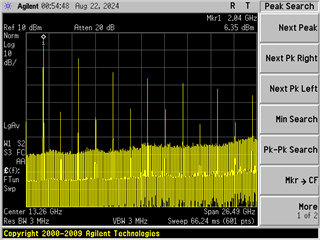
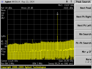
1.When we set as below, disable the tracking filter(with DBLR_CAL_EN=0), the output power will be lost in some frequency area between 11GHz to 19GHz, it is showed in the pic.

a. Program INSTCAL_PLL_NUM, PLL_N, PLL_NUM and PLL_DEN (if their value have change)
b. Program R0 (with FCAL = 0, DBLR_CAL_EN = 0) to change VCO frequency

output from 11GHz to 19GHz

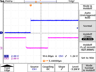
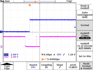
2.When we set as below, enable the tracking filter(with DBLR_CAL_EN=1), the Frequency Lock indicator LD signal will remain to low when we swtich the frequency point in a very tiny time, just like several hundreds of microseconds.

a. Program INSTCAL_PLL_NUM, PLL_N, PLL_NUM and PLL_DEN (if their value have change)
b. Program R0 (with FCAL = 0, DBLR_CAL_EN = 0) to change VCO frequency

Can anyone help to solve the problem when we want to quickly switching the frequency points between 2GHz to 20GHz. Thanks a lot.

  • Hi Lucas,

    In step 3, did you set INSTCAL_DBLR_EN = 1?

    After step 12, did you see the LD pin turn HIGH? If not, we need to program RESET = 1 to reset LMX2820. After it is reset, repeat step 8 to 12.

    This is a proven programming sequence. Here is the test data using this sequence.

    Spectrum at 2GHz and 20GHz.

    Lock time from 20GHz to 2GHz.

    Lock time from 2GHz to 20GHz.

  • Hi Neol, 

    Thanks a lot for your kindly reply. Please help to correct the sequence so we can solve this problem.

    From step 1 to step 8, we set as below:

    reg_r0 <= 24'h004070;
    reg_r1 <= 24'h0157A0;
    reg_r2 <= 24'h0281F4;
    reg_r3 <= 24'h030041;
    reg_r4 <= 24'h044204;
    reg_r5 <= 24'h050032;
    reg_r6 <= 24'h060A43;
    reg_r7 <= 24'h070000;
    reg_r8 <= 24'h08C802;
    reg_r9 <= 24'h090005;
    reg_r10 <= 24'h0A0000;
    reg_r11 <= 24'h0B0602;
    reg_r12 <= 24'h0C0408;
    reg_r13 <= 24'h0D0038;
    reg_r14 <= 24'h0E3001;
    reg_r15 <= 24'h0F2001;
    reg_r16 <= 24'h10171E;
    reg_r17 <= 24'h1115C0;
    reg_r18 <= 24'h120000;
    reg_r19 <= 24'h132120;
    reg_r20 <= 24'h14272C;
    reg_r21 <= 24'h151C64;
    reg_r22 <= 24'h16E2BF;
    reg_r23 <= 24'h171102;
    reg_r24 <= 24'h180E34;
    reg_r25 <= 24'h190624;
    reg_r26 <= 24'h1A0DB0;
    reg_r27 <= 24'h1B8001;
    reg_r28 <= 24'h1C0639;
    reg_r29 <= 24'h1D318C;
    reg_r30 <= 24'h1EB18C;
    reg_r31 <= 24'h1F0401;
    reg_r32 <= 24'h201401;
    reg_r33 <= 24'h210000;
    reg_r34 <= 24'h220010;
    reg_r35 <= 24'h233100;
    reg_r36 <= 24'h24004B;
    reg_r37 <= 24'h250500;
    reg_r38 <= 24'h260001;
    reg_r39 <= 24'h2786A0;
    reg_r40 <= 24'h280000;
    reg_r41 <= 24'h290000;
    reg_r42 <= 24'h2A0000;
    reg_r43 <= 24'h2B0000;
    reg_r44 <= 24'h2C0000;
    reg_r45 <= 24'h2D0000;
    reg_r46 <= 24'h2E0300;
    reg_r47 <= 24'h2F0300;
    reg_r48 <= 24'h304180;
    reg_r49 <= 24'h310000;
    reg_r50 <= 24'h320080;
    reg_r51 <= 24'h33203F;
    reg_r52 <= 24'h340000;
    reg_r53 <= 24'h350000;
    reg_r54 <= 24'h360000;
    reg_r55 <= 24'h370002;
    reg_r56 <= 24'h380001;
    reg_r57 <= 24'h390001;
    reg_r58 <= 24'h3A0000;
    reg_r59 <= 24'h3B1388;
    reg_r60 <= 24'h3C01F4;
    reg_r61 <= 24'h3D03E8;
    reg_r62 <= 24'h3E0000;
    reg_r63 <= 24'h3FC350;
    reg_r64 <= 24'h400080;
    reg_r65 <= 24'h410000;
    reg_r66 <= 24'h42003F;
    reg_r67 <= 24'h431000;
    reg_r68 <= 24'h440020;
    reg_r69 <= 24'h450011;
    reg_r70 <= 24'h4600FE;
    reg_r71 <= 24'h470000;
    reg_r72 <= 24'h480000;
    reg_r73 <= 24'h490000;
    reg_r74 <= 24'h4A0000;
    reg_r75 <= 24'h4B0000;
    reg_r76 <= 24'h4C0000;
    reg_r77 <= 24'h4D0608;
    reg_r78 <= 24'h4E0011;
    reg_r79 <= 24'h4F002E;
    reg_r80 <= 24'h5001C0;
    reg_r81 <= 24'h510000;
    reg_r82 <= 24'h520000;
    reg_r83 <= 24'h530F00;
    reg_r84 <= 24'h540040;
    reg_r85 <= 24'h550000;
    reg_r86 <= 24'h560040;
    reg_r87 <= 24'h57FF00;
    reg_r88 <= 24'h5803FF;
    reg_r89 <= 24'h590000;
    reg_r90 <= 24'h5A0000;
    reg_r91 <= 24'h5B0000;
    reg_r92 <= 24'h5C0000;
    reg_r93 <= 24'h5D1000;
    reg_r94 <= 24'h5E0000;
    reg_r95 <= 24'h5F0000;
    reg_r96 <= 24'h6017F8;
    reg_r97 <= 24'h610000;
    reg_r98 <= 24'h621C80;
    reg_r99 <= 24'h6319B9;
    reg_r100 <= 24'h640533;
    reg_r101 <= 24'h6503E8;
    reg_r102 <= 24'h660028;
    reg_r103 <= 24'h670014;
    reg_r104 <= 24'h680014;
    reg_r105 <= 24'h69000A;
    reg_r106 <= 24'h6A0000;
    reg_r107 <= 24'h6B0000;
    reg_r108 <= 24'h6C0000;
    reg_r109 <= 24'h6D0000;
    reg_r110 <= 24'h6E001F;
    reg_r111 <= 24'h6F0000;
    reg_r112 <= 24'h70FFFF;
    reg_r113 <= 24'h710000;
    reg_r114 <= 24'h720000;
    reg_r115 <= 24'h730000;
    reg_r116 <= 24'h740000;
    reg_r117 <= 24'h750000;
    reg_r118 <= 24'h760000;
    reg_r119 <= 24'h770000;
    reg_r120 <= 24'h780000;
    reg_r121 <= 24'h790000;
    reg_r122 <= 24'h7A0000;

    From Step 9 to Step 12, we set as below:

    spi_data <= 24'h0157A1;
    spi_data <= 24'h6A0400;
    spi_data <= 24'h6B0000;
    spi_data <= 24'h6C0000;
    spi_data <= 24'h6D0000;
    spi_data <= 24'h6A0602;
    spi_data <= 24'h6A0E02;
    spi_data <= 24'h6A0602;
    spi_data <= 24'h6A0603;
    spi_data <= 24'h6A0E03;
    spi_data <= 24'h6A0603;
    spi_data <= 24'h6A0604;
    spi_data <= 24'h6A0E04;
    spi_data <= 24'h6A0604;
    spi_data <= 24'h6A0605;
    spi_data <= 24'h6A0E05;
    spi_data <= 24'h6A0605;
    spi_data <= 24'h6A0606;
    spi_data <= 24'h6A0E06;
    spi_data <= 24'h6A0606;
    spi_data <= 24'h6A0607;
    spi_data <= 24'h6A0E07;
    spi_data <= 24'h6A0607;
    spi_data <= 24'h6A0000;
    spi_data <= 24'h004030;

    spi_data <= 24'h004020;

  • Hi Lucas,

    What is your reference clock frequency?

    In step 1 to 8, did you program the registers in descending order? That is, from R122 to R0.