This thread has been locked.

If you have a related question, please click the "Ask a related question" button in the top right corner. The newly created question will be automatically linked to this question.

LMK04821: LMK04821 out of lock

Part Number: LMK04821

Tool/software:

I need an external input of 10M (OSCin) and an output of 1536M clock to the ADC chip, but there is a out of lock issue.

Testing has found that when an external input clock of 100M is used, LMK04821 can lock normally, and the frequency measured by the spectrometer output is also correct; When the external input is 10M, I found that LMK04821 tends to lock as the amplitude increases. When I tested it, I gave it from 0dBm to 10dBm. When I gave it 10dBm, the lock could occur, but it would out of lock. I did not test for higher amplitudes. When I gave 10dBm, I observed that the output frequency 1536M on the spectrum was also the expected frequency, but in fact, there would be frequency deviation when the amplitude was measured;
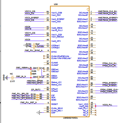
My question
① Can the register values configured using software tools match the external 10M input;
② Can the external 10M input be matched by modifying the register configuration of LMK04821 (such as matching resistor resistance or filter resistance)
③ How should the OSCin/OSCin * pin of LMK04821 be terminated on external hardware in a conventional design? Currently, we have a single ended input (from OSCin)

  • Hello,

    I apologize for the delay, I will get back to you early next week.

    Regards,

    Will

  • OK!Thank you very much.

  • Vayne,

    Is your input a sine wave?

    I cannot tell, but if OSCin is only single ended, then you should change the OSCin termination.  

    You should remove the 100 ohm termination and ground the unused pin with a decoupling capacitor.  If your single ended input swing is less than 2.4V then you can just leave the input AC coupled.  If it is greater than 2.4 you can add a resistor to ground to reduce the swing to under 2.4V but keeping it as close to 2.4V as you can.  

    Your issue is a result of the low slew rate of your 10MHz sine input.  Even at the maximum input voltage of 2.4Vpp. Slew rate = 2*pi*f*Vpp = .15V/ns which is below the recommended slew rate of .5V/ns.  You should still be able to lock, but your performance will slightly degrade.  


    To truly mitigate the slew rate problem due to sine wave inputs you could use an LMK1C1102 buffer before the input that will force the output into a square wave. 

    Let me know if you have any questions.

    Regards,

    Will

  • Yes, I am inputting a sine wave. If it is a square wave, how many appropriate levels should I input? I tried a high level of 2V and a low level of 0V, with an impedance of 50 ohms input

  • Vayne,

    If it is a single ended square wave, the input voltage is less relevant because square waves should ideally have a sharp transition from high to low and vise versa.  Although maximizing the input voltage to 2.4Vpp will still have the best slew rate.

    Regards,

    Will