This thread has been locked.
If you have a related question, please click the "Ask a related question" button in the top right corner. The newly created question will be automatically linked to this question.
Tool/software:
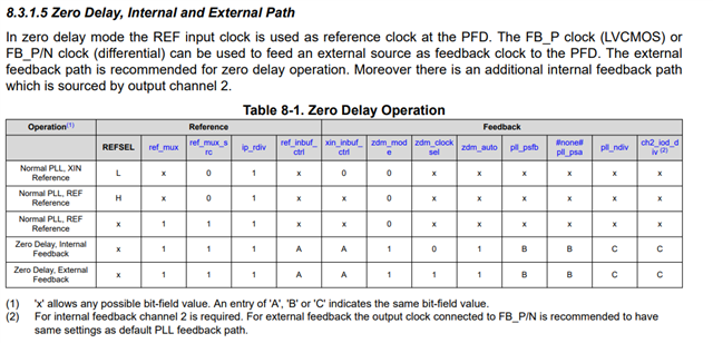
When using REFP/N as the reference, I'm seeing that the phase between the output clocks and the input reference appears to depend on the reference frequency.
I think I've programmed the PLL correctly; I have ip_rdiv set to 1 ; I'm setting pll_ndiv and pll_psfb to get f_vco in the allowed range. My input frequency is between 1 and 100 MHz. I have the sync_en bits set.
When I change the input frequency, I apply new PLL parameters as required and do a re-sync. What I observe is that the relative phase between the reference and output clocks is highly dependent on the frequency.
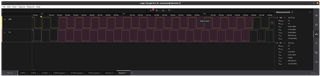
To illustrate, when the input clock is 5 MHz I get this:
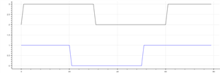
And when it's 30 MHz I get this:
Top (black) is the input reference, bottom (blue) is the PLL output clock. In this case, output frequency = input frequency but that's just to better illustrate the issue; in my application that's not always the case.
As I increase the reference frequency, the phase offset moves in a very regular, monotonic manner.
The PLL is locked (it claims to be, and it appears to be), and this is 100% reproducible (for a given frequency I always get the same phase).
Is this the intended behaviour? Is there anything I can do to get a fixed phase relationship?
I know I can use output sync_delay feature but I don't think that's a complete solution since the adjustment is rather coarse and limited in range.
Jean-Pierre,
If you would like a fixed phase relationship between the input and the output, you need what is called Zero-Delay Mode (ZDM).
I will also note that the CDCI6214 is not recommended for new designs, we instead recommend the CDCE6214, which is pin compatible (and also offers ZDM).
Thanks,
Kadeem
Thank you. I have tried ZDM but am unable to get a proper clock output with it. I need to use the internal feedback option. I have set everything as per Table 1, and the PLL claims to be locked, yet the output clock is running faster than the reference clock: the reference is 5.00 MHz and the output is 5.06 MHz (the PLL is programmed to generate output = input).
I am confused by how ZDM is supposed to work- according to Table 1 I must set zdm_auto, which means that pll_ndiv and pll_psfb are automatically calculated. However Table 1 also says that I must set pll_psa to pll_psfb and ch2_iod_div to pll_ndiv; what is the procedure for this? It's unclear to me which of these are to be set by the user, and which are set by the PLL itself, and what order must be followed. Can you clarify?
Jean-Pierre,
Can you provide your configuration file from TICS Pro, or a register dump? I can evaluate this on an EVM and let you know if I see any issues.
Thanks,
Kadeem
Certainly, here is the register dump:
GENERIC0 (0x00): 0x3100
GENERIC1 (0x01): 0x6b82
GENERIC2 (0x02): 0x0050
GENERIC3 (0x03): 0x0000
POWER0 (0x04): 0x005d
POWER1 (0x05): 0x0008
STATUS0 (0x06): 0x152c
STATUS1 (0x07): 0x0c0f
STATUS2 (0x08): 0x0001
STATUS3 (0x09): 0x0000
EEPROM0 (0x0a): 0x0000
EEPROM1 (0x0b): 0x0000
EEPROM2 (0x0c): 0x0000
EEPROM3 (0x0d): 0x0000
EEPROM4 (0x0e): 0x0000
STARTUP0 (0x0f): 0xa137
STARTUP1 (0x10): 0x921f
STARTUP2 (0x11): 0x26c4
unknown (0x12): 0xa001
unknown (0x13): 0x0000
unknown (0x14): 0x0001
unknown (0x15): 0x0000
unknown (0x16): 0x0000
unknown (0x17): 0x0505
REV0 (0x18): 0x0601
unknown (0x19): 0x0406
INPUT0 (0x1a): 0x8b1a
INPUT1 (0x1b): 0x0001
INPUT_DBG0 (0x1c): 0x0000
PLL0 (0x1d): 0x0078
PLL1 (0x1e): 0x5140
PLL2 (0x1f): 0x1e72
unknown (0x20): 0x0000
PLL4 (0x21): 0x0007
unknown (0x22): 0x0050
CH1_CTRL0 (0x23): 0x8000
CH1_CTRL1 (0x24): 0x0000
CH1_CTRL2 (0x25): 0x0078
CH1_CTRL3 (0x26): 0x0405
CH1_CTRL4 (0x27): 0x0a65
CH1_CTRL5 (0x28): 0x0008
CH2_CTRL0 (0x29): 0x8000
CH2_CTRL1 (0x2a): 0x0000
CH2_CTRL2 (0x2b): 0x0078
CH2_CTRL3 (0x2c): 0x0401
CH2_CTRL4 (0x2d): 0x0a65
CH2_CTRL5 (0x2e): 0x0008
CH3_CTRL0 (0x2f): 0x8000
CH3_CTRL1 (0x30): 0x0000
CH3_CTRL2 (0x31): 0x0078
CH3_CTRL3 (0x32): 0x0405
CH3_CTRL4 (0x33): 0x0a65
CH3_CTRL5 (0x34): 0x0008
CH4_CTRL0 (0x35): 0x8000
CH4_CTRL1 (0x36): 0x0000
CH4_CTRL2 (0x37): 0x0004
CH4_CTRL3 (0x38): 0x0481
CH4_CTRL4 (0x39): 0x0a65
CH4_CTRL5 (0x3a): 0x0008
CHX_CTRL0 (0x3b): 0x0009
CHX_CTRL1 (0x3c): 0x0010
CHX_CTRL2 (0x3d): 0x1000
CHX_CTRL3 (0x3e): 0x4210
CHX_CTRL4 (0x3f): 0x0210
unknown (0x40): 0x000d
unknown (0x41): 0x0f34
unknown (0x42): 0x0000
unknown (0x43): 0x0020
unknown (0x44): 0x0000
unknown (0x45): 0x0000
unknown (0x46): 0x0000
and here are the measured reference and output clocks: reference is 5 MHz, output is 5.063 MHz.
Thank you. We will take a look on the bench and get back to you by the end of the week.
Best,
Cris
Jean-Pierre,
The bit pdn_ch2 is set to a 0. ZDM will not work when Channel 2 is disabled. Setting this bit to a 1, with no other changes, resolves the issue on my end.
Thanks,
Kadeem
Thank you for catching that! This takes care of the original issue (variable phase) that I had.
I still don't understand the zdm_auto bit. According to Table 1, it needs to be set for zero-delay mode. However I get the same behaviour (output clocks are the same) whether I have it set or clear. In both cases I manually set pll_ndiv and pll_psfb.
Is it ok to leave zdm_auto=0?
Jean-Pierre,
The zdm_auto bit is meant to automatically control the values of pll_ndiv and pll_psfb in zero-delay mode.
However, most configurations set these bits properly for zero-delay mode already - when this is the case, the bit can be left as a 0 or as a 1.
Thanks,
Kadeem