This thread has been locked.

If you have a related question, please click the "Ask a related question" button in the top right corner. The newly created question will be automatically linked to this question.

LMK05318B: Cannot DPLL lock - PPS and 24 MHz input, 40 MHz clock output

Part Number: LMK05318B
Other Parts Discussed in Thread: USB2ANY, , LMK05318, LMK5B33216

Tool/software:

We have implemented the LMK05318B for use in a digital carrier board, to provide a reference 40 MHz set of signals to an RFIC and FPGA. We use a 24 MHz XO that has a +/- 2.5ppm accuracy and a GPS receiver from u-Blox to provide a PPS input.

I'm attaching our TCS file: https://drive.google.com/file/d/1yKAOyZ3CsoECdfFrOq-e86CL_EgNNyhQ/view?usp=drive_link

And the carrier board's schematic page: https://drive.google.com/file/d/1t9dCRsU3_SJ7NDb1n1_-0KC1_oprw6b2/view?usp=sharing

We have the following status bits when we flash our LMK chip:

  • 'LOL_PLL1': 1
  • 'LOL_PLL2': 1
  • 'LOS_FDET_XO': 0
  • LOS_XO': 0
  • 'HIST': 0
  • 'HLDOVR': 1
  • 'LOFL_DPLL': 1
  • 'LOPL_DPLL': 1
  • 'LOR_AMP': 0
  • 'LOR_FREQ': 0
  • 'LOR_MISSCLK': 0
  • 'REFSWITCH': 0

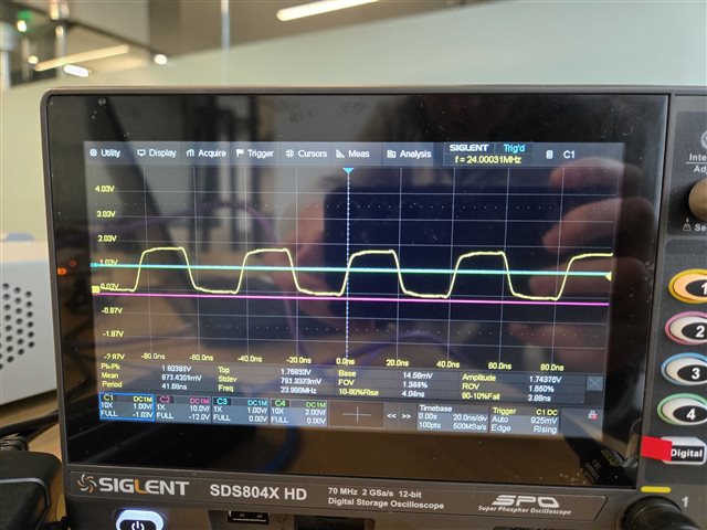
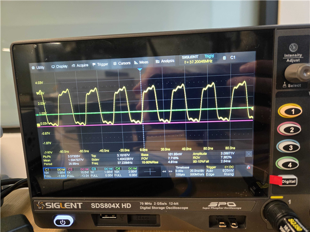
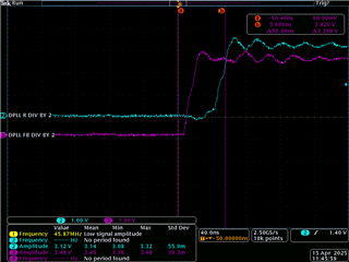
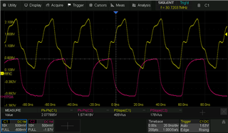
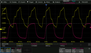
Meaning that our LMK chip's DPLL cannot lock on, even after waiting for several hours (~12 hours) to the lock to be established. We have measured the pps signal and XO input and they are valid signals, using an oscilloscope. The LDO power supplies are working properly.

Any input and recommendations to achieve a DPLL lock would be appreciated, or further debugging steps.

  • Hi Quint,

    Thanks for the update. I will reach back after testing with the 10% 1PPS pulse in the next few days.

    Regards,

    Jennifer

  • Hi Jennifer,

    I have been working on an alternate configuration, using the following settings:

    Software configuration used in TICS Pro

    5710.config.tcs

    Status indications:

    • 'LOL_PLL1': 1
    • 'LOL_PLL2': 1
    • 'LOS_FDET_XO': 0
    • LOS_XO': 0
    • 'HIST': 0
    • 'HLDOVR': 1
    • 'LOFL_DPLL': 1
    • 'LOPL_DPLL': 1
    • 'LOR_AMP': 0
    • 'LOR_FREQ': 0
    • 'LOR_MISSCLK': 0
    • BAW is Unlocked (R80[7] readout)
    • PRIREF_VALSTAT is 0
    • SECREF_VALSTAT is 0

    Scope shots of the XO (measured directly next to the LMK chip):

    Scope shot of the 30.72 MHz SECREF input:

    This is confirmed to be the correct SECREF input when measured on Pin 10 (SECREF_P) of the LMK05318B.

    We expected this configuration to lock a lot faster, but even after hours, we see no change in the status results. We have also attempted to soft-reset the chip multiple times, with no change in the results.

    We have successfully gotten a DPLL lock on the LMK evaluation kit using these settings, but are unable to get a lock with our custom board.

    Can you please review our .tcs file and let us know if we have made any errors or if you have any further recommendations?

    Thank you,

    Arpad.

  • Hi Arpad,

    I also cannot get the DPLL to lock with that configuration. Since this is using a higher frequency signal (> 5 MHz), my suggestion is to use the EVM default configuration as the base config then modify the wizard settings.

    That is what I did to get the config below and the DPLL locks. With this higher frequency of 30.7 MHz, the DPLL frequency and phase lock time should not take more than a few seconds, no need to wait several hours.

    Please try this config:

    2025-04-30, xo=24M, secref=30.72MHz.tcs

    Another area of concern is that LOL_PLL1 and LOL_PLL2 are set. Also, BAW_LOCK and SECREFVAL_STAT are cleared. With your config, I was able to get BAW_LOCK to set when the SECREF input is not present (this is the expected behavior). Also, with your config, I see that LOL_PLL1 and LOL_PLL2 are cleared in my setup (this is the expected behavior).

    The priority of debug is to check LOL_PLLx --> BAW_LOCK --> SECREFVAL_STAT --> DPLL LOFL --> DPLL_LOPL.

    Starting with LOL_PLLx first because the DPLL will not lock if APLL1 is unlocked:

    • I don't see an issue with the XO input waveform. That looks within spec. Plus the LOS_XO and LOS_FDET_XO are 0 which tells me the XO input is within frequency (10 MHz to 100 MHz) and amplitude spec.
      • With that said, can you confirm that the LOS_XO_FDET_INTR and LOS_XO_INTR remain cleared? If these bits are toggling then this can indicate something is wrong with the XO input. If they are not toggling (stay cleared), then the next step is to examine the APLLs.
    • LOL_PLLx gets cleared when the PLL charge pump tuning voltage has reached the required threshold. This is a coarse lock detect as it relies on the threshold voltage to clear. From your readback, the APLLs are reporting unlocked. This can be due to the a few reasons:
      • APLL registers are not configured properly. --> Confirm the registers are programmed as expected.
      • Supply pins are not receiving power properly. --> Probe all VDDx and VDDO_x pins (should be nominal 3.3V). Also, probe LF1 and LF2 to assess the state of the PLL tuning voltage. Probe CAP_PLL1 and CAP_PLL2, the LDO voltages of the PLLs (should be around 2.65V).
      • XO input is faulty...see next bullets.
    • BAW_LOCK gets cleared when the VCO1 frequency and XO input frequency is within the register defined threshold (I may have explained this previously). This is a fine detector as it's based on frequency not voltage.
      • If BAW_LOCK is set, then either the BAW_LOCK and APLL register settings are not written properly or the XO input frequency is faulty.

    Please examine the above debug items before we proceed with the remainder: SECREFVAL_STAT --> DPLL LOFL --> DPLL_LOPL.

    The other thing to consider--maybe the LMK05318B is not soldered down properly?

    • Does the DPLL lock with this setup below? Essentially, we use all the external signals that would go to the custom board but the only thing that changes is the PCB used. That way we can narrow down if the PCB is the cause.

    Regards,

    Jennifer

  • Hi Jennifer,

    We have a few updates as well as a few questions:

    We are now able to lock onto 30.72MHz reference input with 24MHz 2.5ppm TCXO, using the following config:0207.config.tcs

    So we are now trying to achieve lock with 1PPS on the EVM, which leads to the questions:

    1) Odd behavior: Can you help us interpret what we see in this video? Here's the event timeline:

    0:17: Start reset:
    0:27: PRIREF VALSTAT -> HIGH

    0:28: DPLL_FB starts to oscillate at 1Hz. First time switching high

    0:29: DPLL_R goes high for first time. Oscillating 180 degrees out of phase from DPLL_FB
    0:35: Lose BAW_LOCK & measured output frequency deviates from 40M.

    Is presume this is not expected behavior?

    I also tried disabling tuning word history, thinking that perhaps we had bad tuning words that were throwing off the DPLL frequency once it became locked, but that didn't seem to change anything.

    I've tried regenerating everything in the config from scratch (rerunning frequency config, rerunning DPLL script, etc.) but without any change. Here's a video of the PLL1_NUM_STAT while repeating the sames steps from above. It makes a single large jump exactly when the frequency changes from 40MHz to 39.xxMHz.

    Here's the TICS config I'm using. Only small modifications from the one you previously provided us with:

    0207.config.tcs

    2) I see that 1PPS config has fastlock disabled, and the following rec:

    Should Fastlock always be disabled when using 1PPS?

    3) I know that Zero Delay Mode was removed from TICS for the 05318B because it's not "true ZDM" and was confusing people, but ensuring 1PPS input and 1PPS output do not have a phase shift is going to be necessary for us. Could you advise on the necessary changes to enable ZDM with the above config?

    4) My current understanding is that the Step 6 settings (excluding tuning word history) are ONLY involved in determining the thresholds for which the LOPL_DPLL, LOFL_DPLL, and BAW_LOCK flag are set/cleared, and do not actually affect the internet locking of the PLLs (and thus have no effect on the frequency output, lock time, etc.). Is this correct?

    Step 6 Settings

    Thank you!

    Best,

    -Quint

  • Hi Quint,

    If you "zoom in" on the scope by adjusting the time base, can you show the behavior of DPLL R and DPLL FB? Close enough to see only one edge of each signal. Trigger on DPLL R.

    I would need to see how the DPLL FB DIV BY2 is behaving respective to the DPLL R DIV BY 2. It's OK for the two signals two be in-phase or 180 deg out-of-phase as long as we see the two edges aligned. The 180 deg out-of-phase is acceptable on the status signals because the dividers (DIV BY 2) on the two status signals are not SYNCed.

    Something like this:

    Based on the behavior of the APLL NUM STAT, it looks like the DPLL updates are not occurring, at least how it would be expected. It seems that the DPLL isn't tracking the REF properly. The BAW LOCK goes low because the VCO is now tracking the REF not the XO input. If you see the output frequency deviate from 40 MHz, it's because the DPLL is now following the REF input (or trying to follow it).

    Yes, fastlock needs to be disabled for 1PPS. Fastlock is used for higher frequency inputs (like 100 MHz for example) where the DPLL can make a jump by widening the DPLL LBW then narrowing it again to the specified setting. With 1PPS, we don't want to widen it (should stay at 0.1 Hz or 0.01 Hz).

    The "ZDM" option can be used for 1PPS. I'm still working on datasheet updates to rename this feature. Please keep in mind that the open loop ZDM only takes effect once the DPLL has achieved phase and frequency lock. I can provide further instructions on this once we get the DPLL to lock on 1PPS, if that works for you.

    Correct, the lock thresholds should be messed with after confirming the DPLL R and FB dividers are behaving as we expect. Otherwise, leave as default. The tuning word history is used to determine the value of the APLL numerator when the device switches from DPLL lock (outputs lock to REF) to holdover (outputs lock to XO).

    Let me test with your 1PPS configuration.

    Regards,

    Jennifer

  • Hi Jennifer,

    Thanks for the detailed explanation as to our loss of 40MHz lock, I think that helps clarify things. I'm wondering if there is a programming issue (either TICS Pro or user error) that's leading to this issue?

    I'll rerunning the tests with the trigger setup you described & send over shortly.

    Two questions in the meantime:

    1) Were you able to retest the 1PPS with 10% duty cycle? And/or could you test our 1PPS config from above with 10% duty cycle?

    2) If we do use the 30.72 SECREF as our reference input, we will lose the 1PPS timing as discussed earlier. However, we will still have the 1PPS being fed into PRIREF even if it's not used. Is there any way to "forward" this signal (PRIREF) to OUT7 when it is NOT the active reference input? I presume this is not possible as I've seen nothing like it in the datasheet, but wanted to ask just in case...

    Thank you!

    Best,

    -Quint

    EDIT: Sounds good re: ZDM, we won't concern ourselves with it for now. And likewise on the DPLL lock thresholds, we will use defaults until DPLL locking is working smoothly.

  • Hi Quint,

    #1 There's been a delay in getting the test setup running for 10% duty cycle in my lab. Let me try to get results for you by tomorrow.

    #2 I confirm that the forwarding to OUT7 when not the active REF is not an available option on the LMK05318B.

    Regards,

    Jennifer

  • Hi Quint,

    Follow-up on #1 to check the 10% duty cycle...

    I confirm that with the config I sent I'm able to lock with a 10% duty cycle reference.

    For my setup, I use an Agilent 81160A arb gen with the continuous square wave mode option selected. Exact settings are: High level is set to 1.1 V. Low level is set to 5 mV. Duty cycle is 10%. Load Impedance is 50 ohms. Frequency is 1 Hz.

    Regards,

    Jennifer

  • Hi Jennifer,

    Thanks for confirming on the 10% duty cycle.

    I'm having some issues recreating previous results on our eval board and would appreciate any input from you regarding our configuration (attached).

    Overview:

    - 40MHz output on OUT5P and OUT5N only. (OUT7P is now disabled.)

    - Using SECREF only (30.72MHz). Sourced from ublox LEA-M8F (on our PCB, connected via u.FL -> SMA cable). PRIREF is not connected.

    - XO: Exact same 24MHz 2.5ppm TCXO as before.

    Purple trace is XO signal measured across R40 on EVM, and yellow trace is SECREF_P measured across R16 on EVM.

    The main issue is that we are not exiting holdover (presumably because LOR_XO flag is checked), and sometimes not achieving SECREF_VALSTAT as is the case above. Although SECREF is not the smoothest signal (and maybe causing SECREF validation issues), I don't know what is causing XO_P to trigger LOR_XO. The slew rate is slightly below 0.2V/ns, but it's the exact same circuit/test setup as the past few weeks and I haven't had issues with LOR_XO previously. Any input is appreciated, thank you!

    config_no_window_detector.tcs

    Best,

    -Quint

  • Hi Quint,

    Let me check this config and see if there is anything that stands out, register wise.

    Regards,

    Jennifer

  • Hi Quint,

    I also get the LOS_XO bit set with your config. I saw that R43[2] =1 which should be 0. Once I set it to 0, I get the LOS_XO to clear.

    This bit is reserved and routes either the XO input or the REF input to the APLL1 input. The recommended value is 0 to route the XO input to APLL1.

    I'm not sure exactly how you reached this state since the GUI does not modify that register bit.

    Regards,

    Jennifer