This thread has been locked.

If you have a related question, please click the "Ask a related question" button in the top right corner. The newly created question will be automatically linked to this question.

LMK04828:LMK04828 Multi-board synchronization problem

Part Number: LMK04828

Tool/software:

I want to use a master LMK04828 to generate 7.8125M clock and input it to the in0 port of two LMK04828 chips for multi-board synchronization.

The clocks of the two slave machines I tested were basically synchronized but the frequency seemed unstable and there was a lot of jitter

0310A.pdf

Master/slave LMK circuit schematic diagram, the slave LMK only uses the 100M crystal oscillator on the board and the IN0-7.8125M output of the master LMK

master LMK04828-7.8125M

The 7.8125M output of the host LMK and the output of the active LMK are synchronized without jitter and connected to the in0 port of the slave LMK through an equal length coaxial cable

The output of the slave LMK 500M is biased and jitter

in0_SD7.8125.tcs

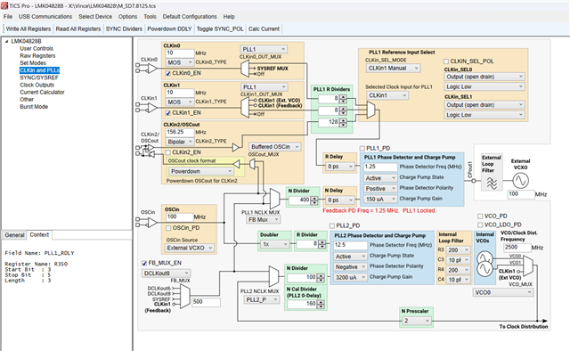
The configuration file of the slave machine

I am not very clear about the configuration of multi-board clock synchronization. I hope you can guide and help me!

  • Hello,

    We will get to you on Monday.

    Thanks,

    Michael

  • Hello, 
    Can you please share the config file for the devices in distribution mode? 

    Just to ensure I understand - you wish to distribute the 7.8125MHz sysref signal? 

    Best regards, 

    Vicente 

  • Hello,
    Yes, my host's SDCLK allocates 7.8125M clock to multiple slaves.

    (The following is the configuration file that generates the 7.8125M synchronous clock.)

    M_SD7.8125.tcs

  • Hello, 
    I don't see this slaves device being in buffer mode. I see both PLLs being used. 

    I understand you're using one LMK04828 and using the internal VCOs to generate a variety of output clocks. 
    From these outputs, a 7.8125MHz clock is going to be fed into more LMK04828s (slaves) that will be operating in buffer mode to fan out this 7.8125MHz SYSREF signal. 

    Is my understanding correct? If it is not - please provide a clock tree or block diagram to better understand what you're trying to implement. 

    Best regards, 

    Vicente 

  • Hello,

    I am sorry that I did not express it clearly. I made a chart to describe the general structure of my plan. The current situation is that the 7.8125M output of the master seems to be stable, while the jitter between the two DCLKS of the secondary output is too large to be completely synchronized. There seems to be some instability in the signal itself.

    Let me also reclassify the configuration files.

    slave1 and slave2:8372.in0_SD7.8125.tcs

    master:8372.M_SD7.8125.tcs

    Can you point out anything that's not clear

  • Hello,

    We we will get to you tomorrow.

    Thanks,

    Michael

  • Hello,

    Could you give me some help? This problem hasn't been well solved yet. It would be great if you could first help me check if there's anything wrong with the configuration files of the master and slave machines. Another one is that I read the documentation of MULTI-LMK SYNC. Maybe it's the Case 1a I'm using that causes the slave output clock to be unstable. I'm trying to change it to Case 2b, but I didn't configure the clock synchronization successfully. I'd like to ask if there is a more detailed documentation about the configuration rules of Case 2b? Thank you!

  • Hello,

    We will be able to replicate this in lab on our boards on Monday.

    Thanks,

    Michael

  • Hello,

    Will there be the same problem when using my master-slave configuration program on your board?

    Thanks

  • Hello,

    Based on your clock tree, this seems like a feasible setup. Your configurations also all look good. 

    Your schematic looks pretty good generally, but there are some shunt terminations on the inputs (i.e. CLK_4208_IN1_CMOS/TCXO_OUT_ATT) that I think are unnecessary, given that your clock source is CMOS. 

    Can you clarify which slave clock output you measured the above scope shot with? If you are outputting from one of the output banks with a SYSREF signal also being driven, there is going to be considerable phase noise degradation - specifically because the SDCLKoutX that are driving 7.8125 MHz are going to result in harmonics at 7.8125 MHz, 15.625 MHz, etc. 

    Additionally, have you looked at the combined LVDS signal at the output? Can you try using a balun to combine the signals into one, or can you try using the math function to subtract the N-signal from the P-signal (this may look closer to the anticipated signal than the two separate measurements of a differential signal)?

    Thanks,

    Michael